Robotic Welding System for Aerospace Industry


The robotic system is designed for TIG and PAW welding of components for aircraft and spacecraft engines. Main parts to be welded include shells, cones, and rings, while the system also supports welding of complex-shaped components. The equipment ensures the highest quality welds necessary for all critical elements of specialized products.
Overall View of the System
System Equipment:
- Welding rotary column for IRS robot with lifting console
- Two-axis welding positioner with clamping tailstock
- Jig for linear welds
- Welding table, Series 16, 2400×1200 mm
- Safety system

System Components
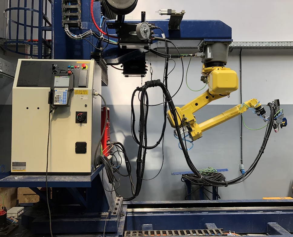
Robot with Controller on Moving Column
Type — Articulated
Number of axes — 6
Payload — 12 kg
Arm reach — 2009 mm
Positioning accuracy — ±0.08 mm
Maximum load — 12 kg
Drive type — Electric servo with AC motor
Mechanical block weight — 250 kg
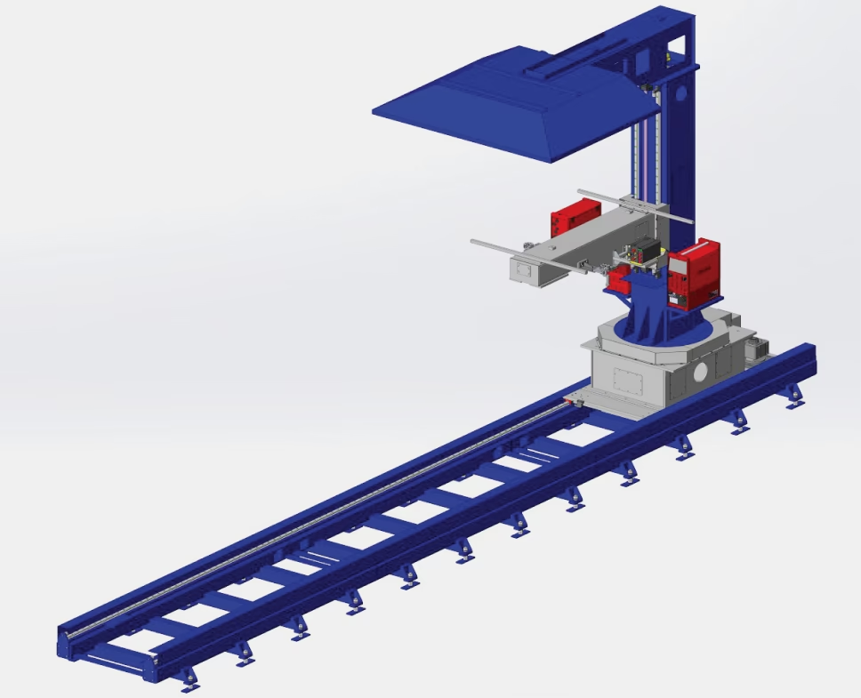
Welding Rotary Column for IRS Robot with Lifting Console
IRS rotary column on linear axis increases the welding robot's working area.
Console reach — 1800 mm
Console travel — 1400 mm
Lift/lower speed — 2 m/min
Rotation range — −90/90°
Rotation speed — 1.5 rpm
Linear travel of column — 6000 mm
Linear speed — 5 m/min

Two-Axis Positioner with Clamping Tailstock
Rigid frame with horizontal and vertical rotation axes. Adjustable tailstock for long parts.
Rotation axes — 2
Payload — 1500 kg
Max rotation speed — 20 rpm
Table rotation range — 600/-600°
Workpiece diameter — up to 2500 mm
Max table tilt speed — 5 rpm
Tilt range — 135°/0°
Positioning accuracy — ±0.08 mm
Distance between tables — 200...2300 mm

Fixture for Linear Welds on Parts with Wall Thickness up to 10 mm
Workpiece diameter — 300...2500 mm
Max workpiece length — 1500 mm
Wall thickness — 0.8...10 mm
Max payload — 1000 kg
Max welding current — 500 A
Required grounding — ≤10 Ω
Compressed air pressure — 0.3...0.6 MPa
Weight — 800 kg
Dimensions — 2800×880×2380 mm

Fixture for Linear Welds on Parts with Wall Thickness 10–20 mm
Max length — 350 mm
Wall thickness — 10...20 mm
Max payload — 200 kg
Max welding current — 500 A
Required grounding — ≤10 Ω
Compressed air pressure — 0.3...0.6 MPa
Weight — 350 kg
Dimensions — 800×700×1700 mm

Welding Power Source with Plasma Module
Supply voltage — 3×400 V ±15%
Frequency — 50/60 Hz
Primary operating power (100% duty cycle) — 17.9 kVA
Current range: TIG — 3-500 A, MMA — 10-500 A
Welding current at 10 min/40°C: 40% duty cycle — 500 A, 60% — 440 A, 100% — 350 A
Open-circuit voltage — 86 V
Operating voltage: TIG — 10.1-30.0 V, MMA — 20.4-37.6 V
Dimensions (L×W×H) — 625×290×705 mm
Weight — 58.2 kg

Laser Seam-Tracking System
Adaptive laser-optical system corrects robot movements, recognizes joint geometry, and adjusts trajectory.
Field of view — 50 mm
Depth of focus — 70 mm
Distance to workpiece — 65 mm
Pixel size — 0.05×0.06 mm
Positioning accuracy — ±0.1 mm
Dimensions — 39.5×118×67 mm
Weight — 0.65 kg
System Operation
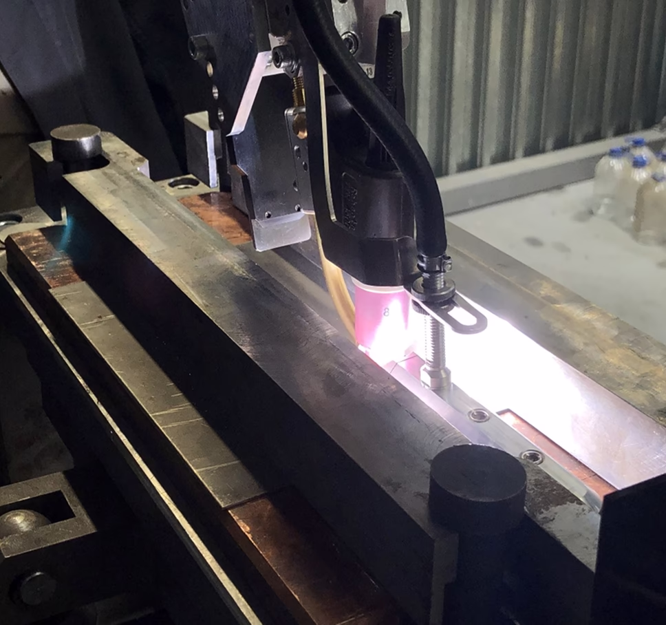
TIG Welding of Samples

TIG Welding of Part

Pilot Arc

Front Side

Weld Penetration
Sample: VT20 Alloy, Thickness — 1.5 mm

Front Side

Weld Penetration
Sample: OT4-1 Alloy, Thickness — 1.0 mm
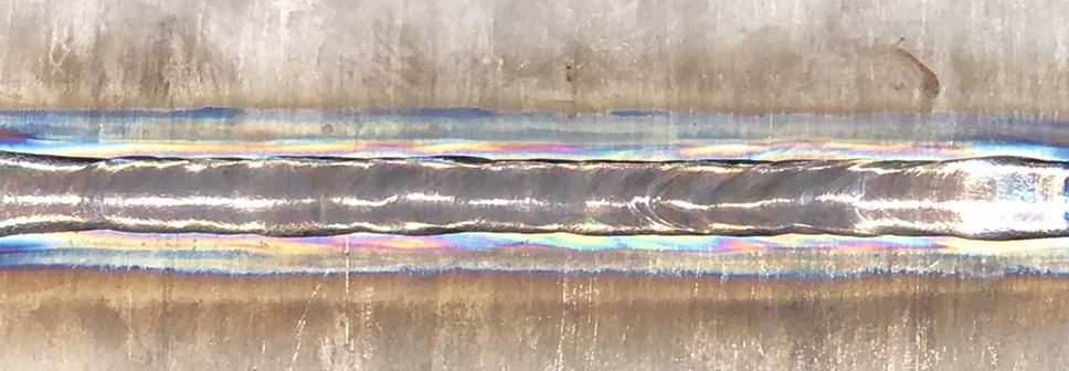
Front Side
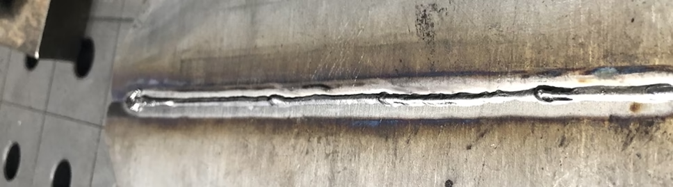
Weld Penetration
Sample: OT4-1 Alloy, Thickness — 10.0 mm, Welded in One Pass Without Edge Preparation
Gallery of completed projects


