Robotic Waterjet Cutting Complex

Purpose: waterjet processing of various metallic and non-metallic materials
Material of workpieces: various grades of steel, plastic, glass, titanium alloys, various heat-resistant alloys, and other materials
Brief description: The robotic complex is designed to perform a range of technological operations: waterjet cutting of workpieces up to 300 mm thick, waterjet turning, and waterjet coating removal. The complex includes: an industrial robot manipulator, a spindle with a turning chuck for waterjet turning, a high-pressure pump, an abrasive feeding system, a waterjet catchment tank, a tooling set for holding small parts, and other subsystems. The complex enables waterjet processing of a wide variety of parts made from different materials, thanks to the robot's 6 degrees of freedom and the coordinate measurement and gap-maintenance system. The delivery package also includes a computer system for preparing control programs for the complex.
General View of the Complex

The robotic waterjet cutting complex can be operated by a single operator.
Main tasks of the operator:
- Installing and securing workpieces
- Finding the zero point of the program using a coordinate measurement system based on a laser rangefinder
- Starting the program in automatic mode from the control panel or operator console
- Monitoring program execution and parameters on the operator panel
- Removing finished parts
- Monitoring and replacing consumables (abrasive, focusing tubes, etc.)
- Visual inspection of the finished parts
- Adjusting work programs
- Starting automatic measurement of the tool coordinates
Main Components of the Complex
- Waterjet catch basin with a quick water level adjustment system
- Industrial robot manipulator
- Storage hopper for the abrasive feeding system
- High-pressure pump
- Slurry removal system
- Fixtures for waterjet cutting of small workpieces
- Industrial robot controller
- Complex control cabinet with panel computer
- Automated operator workstation
- External rotary axis (spindle) for turning operations
- Tool calibration system
- Pneumatic cabinet for blow systems within the robot and water level regulation
Not shown on the diagram:
- Coordinate measurement and gap maintenance system based on a laser rangefinder
- Tool tilt monitoring system (inclinometer)
- Panel computer with operator touchscreen
- High-pressure valve and cutting head
- Visual and acoustic alarm for low abrasive level and other complex statuses
- Dosing hopper for the abrasive feeding system

System Components
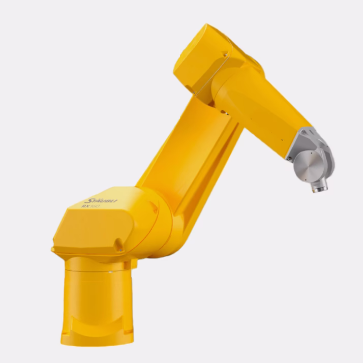
Industrial Robot Manipulator
Max. working radius — 1900 mm
Rated payload — 14 kg
Position repeatability (ISO 9283) — ±0.05 mm
Number of axes — 6
Protection class — IP67
Design — for wet environments
Additional protection — pressurized enclosure
Software — LLC “Intelligent Robot Systems”
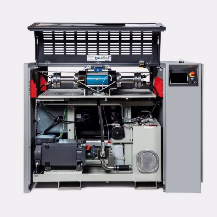
High-Pressure Pump
Output pressure range — 10–400 MPa
Working fluid — water
Type — multiplier
Number of multipliers — 2
Drive — servo drive
Cooling type — water
Operator panel functions — display of current values, status indication, etc.
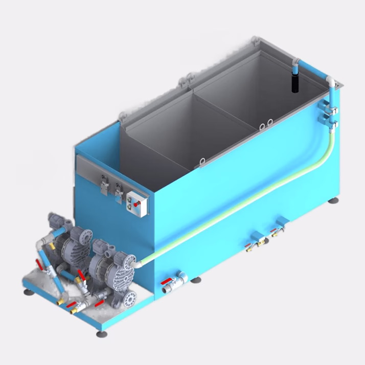
Slurry Removal System
Pump type — pneumatic diaphragm, abrasion-resistant
Number of settling tanks — 2
Sensors — water level sensors, pneumatic line pressure sensors
Control — automatic and manual
Operating temperature range — +5 to +30 °C
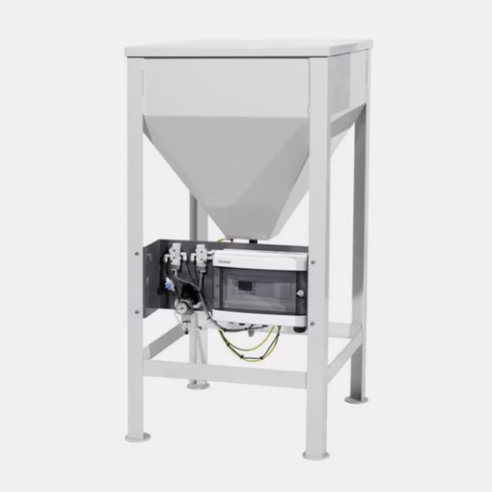
Abrasive Feed System Hopper
Hopper capacity — 1600 kg
Feed rate — 1000 g/min
Abrasive size range — 80–200 mesh
Feeding method — using excess pressure
Low abrasive level alarm
Electronic control system
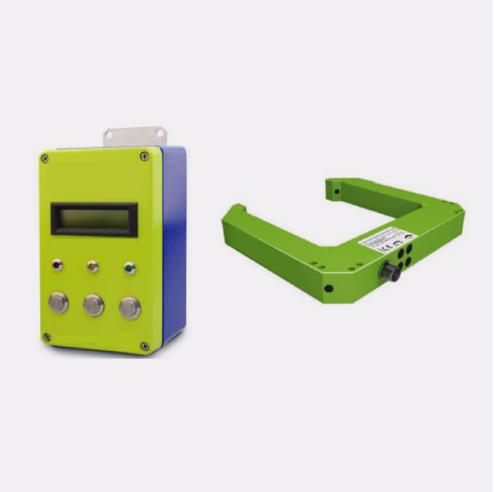
Robot Tool Calibration System
Sensor type
Dual-channel infrared (880 nm), pulsed at 2 kHz
Calibration accuracy — 0.02 mm
Calibration dimensionality — 6D
Calibration time — about 30 seconds
Protection class — IP67

Panel Computer with Operator Touchscreen
Screen diagonal — 10.1 inches
Panel type — touchscreen
Front protection class — IP66
Application software — LLC “Intelligent Robot Systems”

Tool Rotation Angle Monitoring System
Measurement principle — MEMS gyroscope, MEMS accelerometer
Number of measured angles — 2 (x, y)
Measurement range — 0–360°
Protection class — IP68
Vibration resistance — 55 Hz (1 mm)
Shock resistance — 30 g (11 ms)

Laser-Based Gap Maintenance and Coordinate Measurement System
Measurement principle — triangulation
Measurement range — 100–400 mm
Protection class — IP67
Laser safety class (IEC 60825-1) — Class 2
Connector — Rotating M12
Ambient light resistance — >10,000 lux
Vibration resistance — 55 Hz (1 mm)
Repeatability — ±0.1 mm
Waterjet Processing Technological Solutions

Waterjet Cuts
This complex allows cutting various materials up to 300 mm thick. For deep cuts, the robot tool moves at an angle to the workpiece to compensate for taper and jet lag. The robot’s 6 degrees of freedom enable cutting at different heights, creating various orientations, bypassing stepped surfaces, and maneuvering around corners.

Waterjet Turning
The complex can perform waterjet turning of various workpieces, enabling the formation of both cylindrical and curved surfaces with high precision.

Waterjet Turning of Square-Section Workpiece into Cylinder
The robotic waterjet processing complex allows turning square-section workpieces into cylindrical shapes. Unlike traditional lathes, this method avoids excessive wear of the cutting tool while maintaining high precision.
Operation of the Complex

Automatic calibration of the working tool in a special calibration device

Samples produced by waterjet turning

Samples produced by waterjet turning

General view of the catch-bath of the complex

Robot controller cabinet with robot control panel

Control cabinet with panel computer and touchscreen for managing the complex
Gallery of completed projects


