Robotic Laser Welding and Cladding Complex
The robotic complex provides the capability to restore the geometric dimensions of parts of aircraft machines and assemblies in the form of flat parts, rotational bodies, and bodies with surfaces formed by third-order curves using laser welding with or without filler wire and laser powder cladding.
Purpose: restoration of worn parts of aircraft machines and assemblies
Material of parts: stainless steel, titanium and titanium-based alloys, nickel-based alloys, refractory metals
Processing position: lower, horizontal
Technical specifications:
Overall dimensions of the complex (on site) — 8.6×9.5 m
Working chamber dimensions — 5.2×4.4×3.6 m
Maximum laser power — 10 kW
Weldable part thickness — 1.5–10 mm
Minimum width of one weld bead — approx. 0.8 mm
Maximum width of one weld bead — approx. 3.0 mm
Equipment Composition
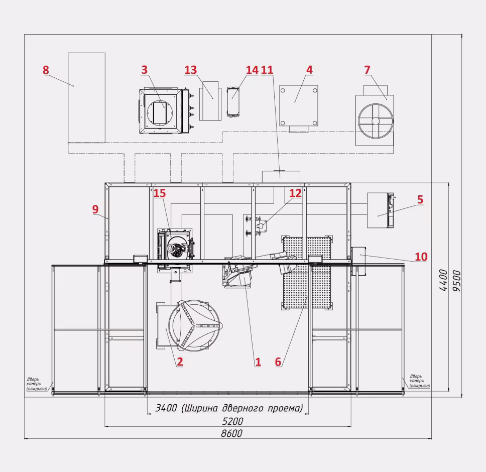
- Industrial robot
- Two-axis positioner (1t capacity) with servo drives
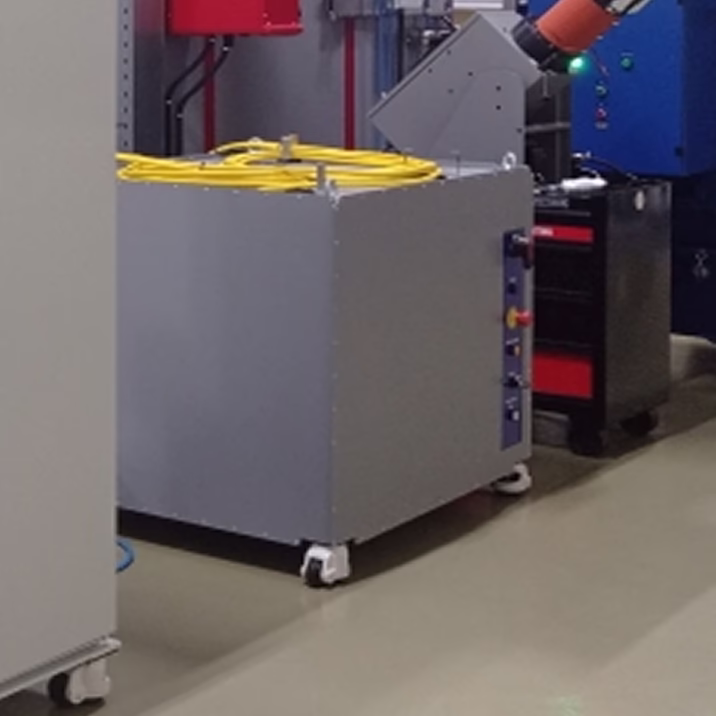
- Filter ventilation unit
- Laser radiation source 10 kW
- Robot controller
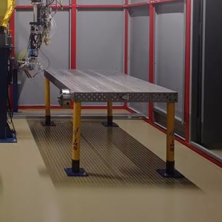
- Assembly-welding table 2400×1200 with a set of stops and clamps No. 3
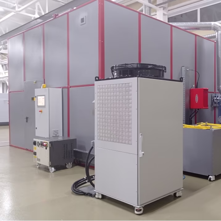
- Industrial chiller for laser source and laser heads
- Air compressor
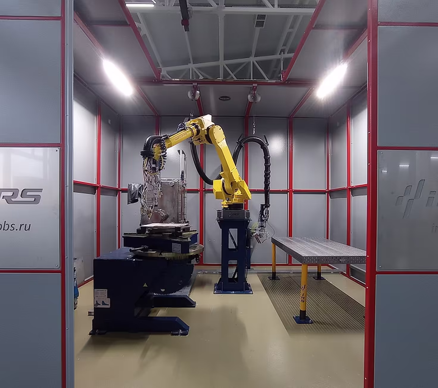
- L-shaped laser welding cabin with sliding doors
- Control cabinet with color touch screen panel
- Main distribution cabinet (VRU)
- Tool change station
- Powder feeder
- Wire feed mechanism
- Chamber with controlled atmosphere and management system
Not shown components:
- Laser head for welding
- Laser head for powder cladding
System Components
Welding Cabin
Overall dimensions (L×W×H) — 5.3×4.6×3.6 m
Laser hazard class (GOST IEC 60825-1-2013) — 4
Loading door — 1 pc.
Type of loading door — sliding, L-shaped
Doorway width — 3.4 m
Personnel door (swing type) with protective viewing window
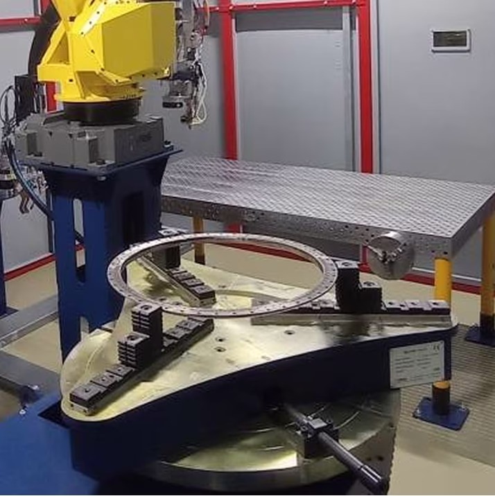
Maximum payload — 1000 kg
Table diameter — 900 mm
Table height above floor — 900 mm
Maximum rotation speed — 6 rpm
Rotation range — −360 to +360°
Maximum tilt speed — 5 rpm
Tilt range — 0 to 130°
Maximum payload — 5000 kg
Table size (L×W) — 2400×1200 mm
Hole diameter / spacing — 16 / 50 mm
Flatness tolerance — ±0.1 mm per 1000 mm
Set of stops and clamps No. 3 included
Ytterbium Fiber Continuous Laser Source with Modulation
Maximum laser beam power — 10 kW
Wavelength — 1070±5 nm
Number of emission channels — 2 pcs.
Fiber diameter in channel 1 (welding) — 200 µm
Maximum power in channel 1 — 10,000 W
Fiber diameter in channel 2 (cladding) — 400 µm
Maximum power in channel 2 — 10,000 W

Chamber with Protective Atmosphere
Dimensions (W×D×H) — 800×600×800 mm
Glove ports — 2 pcs.
Temperature range — −50 to +100°C
Oxygen concentration range — 0–25%
Interface type — color touch HMI panel

Tool Positioning System
Maximum payload — 50 kg
Maximum reach (without grip) — 2050 mm
Positioning repeatability (ISO9283) — ±0.03 mm
Axis rotation angles (1/2/3/4/5/6) — 360/225/440/720/250/720°
Maximum axis speeds (1/2/3/4/5/6) — 175/175/175/250/250/355°/s

RTK Control System
Robot operator console included
Interface type — color touch HMI panel
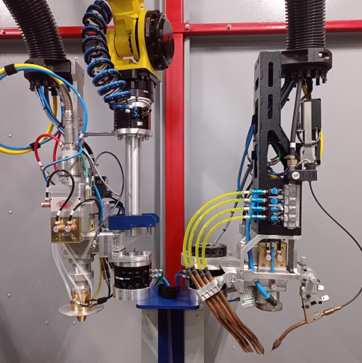
Tool Change Station with Cladding (left) and Welding (right) Laser Heads
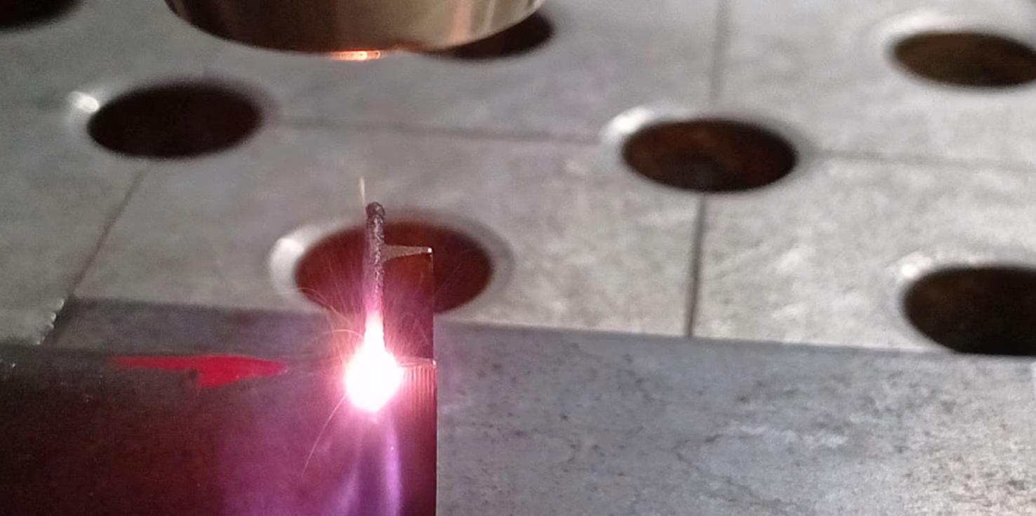
Laser Welding Process
Positioning
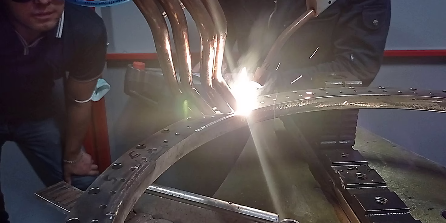
Technology setup
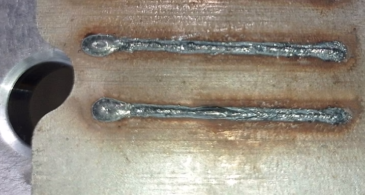
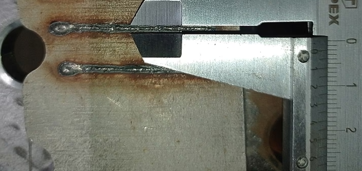
Laser Welding Examples
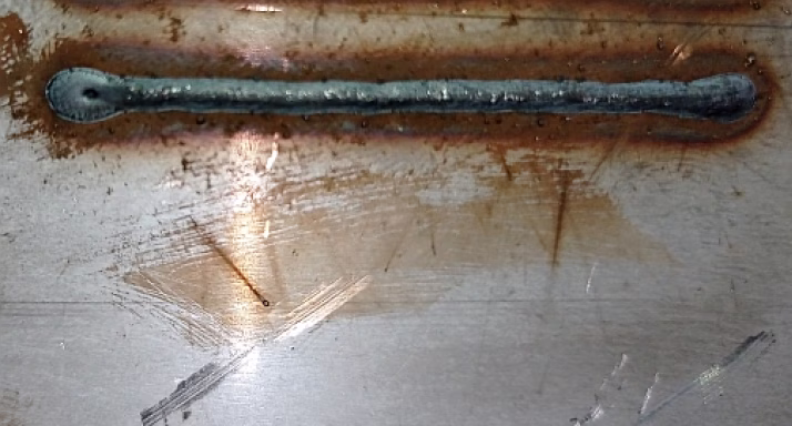
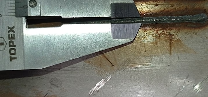
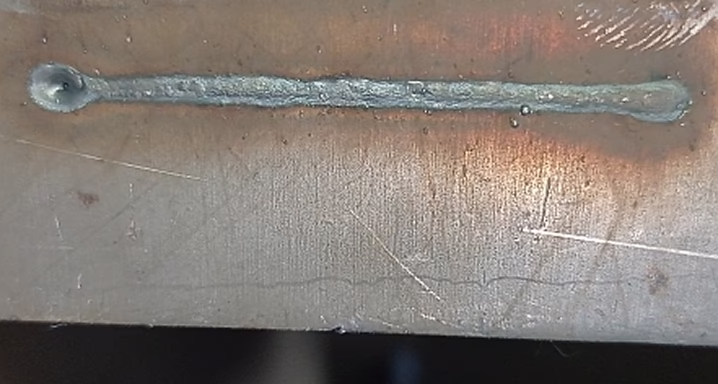
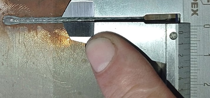
Laser welding 1300 W with filler. Stainless steel 1 mm


Front side of the seam

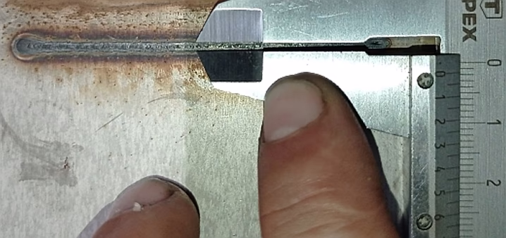
Back side of the seam
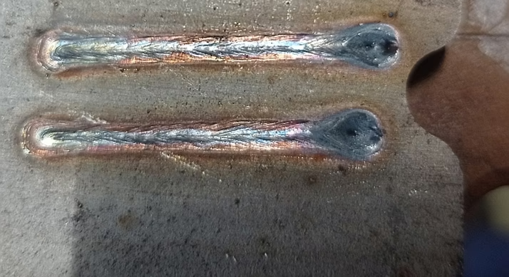
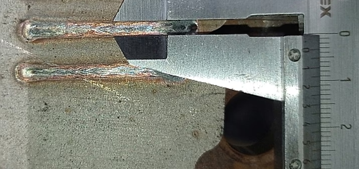
Laser welding 3200 / 4100 W with filler. Heat-resistant stainless steel 2 mm
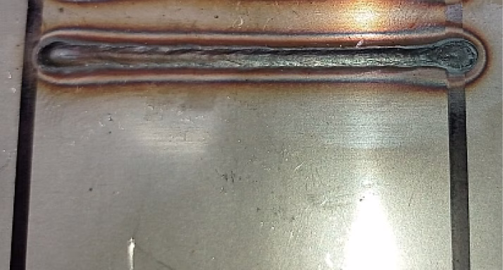
Front side of the seam
Back side of the seam
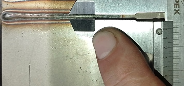
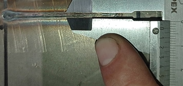
Laser welding 1500 W with filler. Stainless steel 3 mm
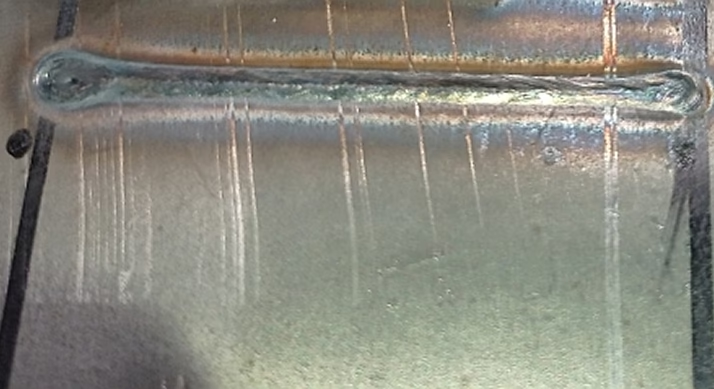
Front side of the seam
Back side of the seam
Laser welding 6000 / 4000 W with filler. Stainless steel 6 mm
Front side of the seam
Back side of the seam
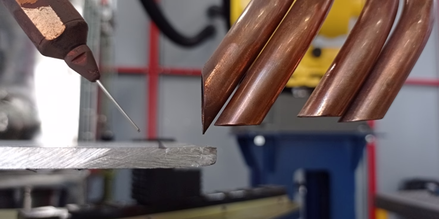
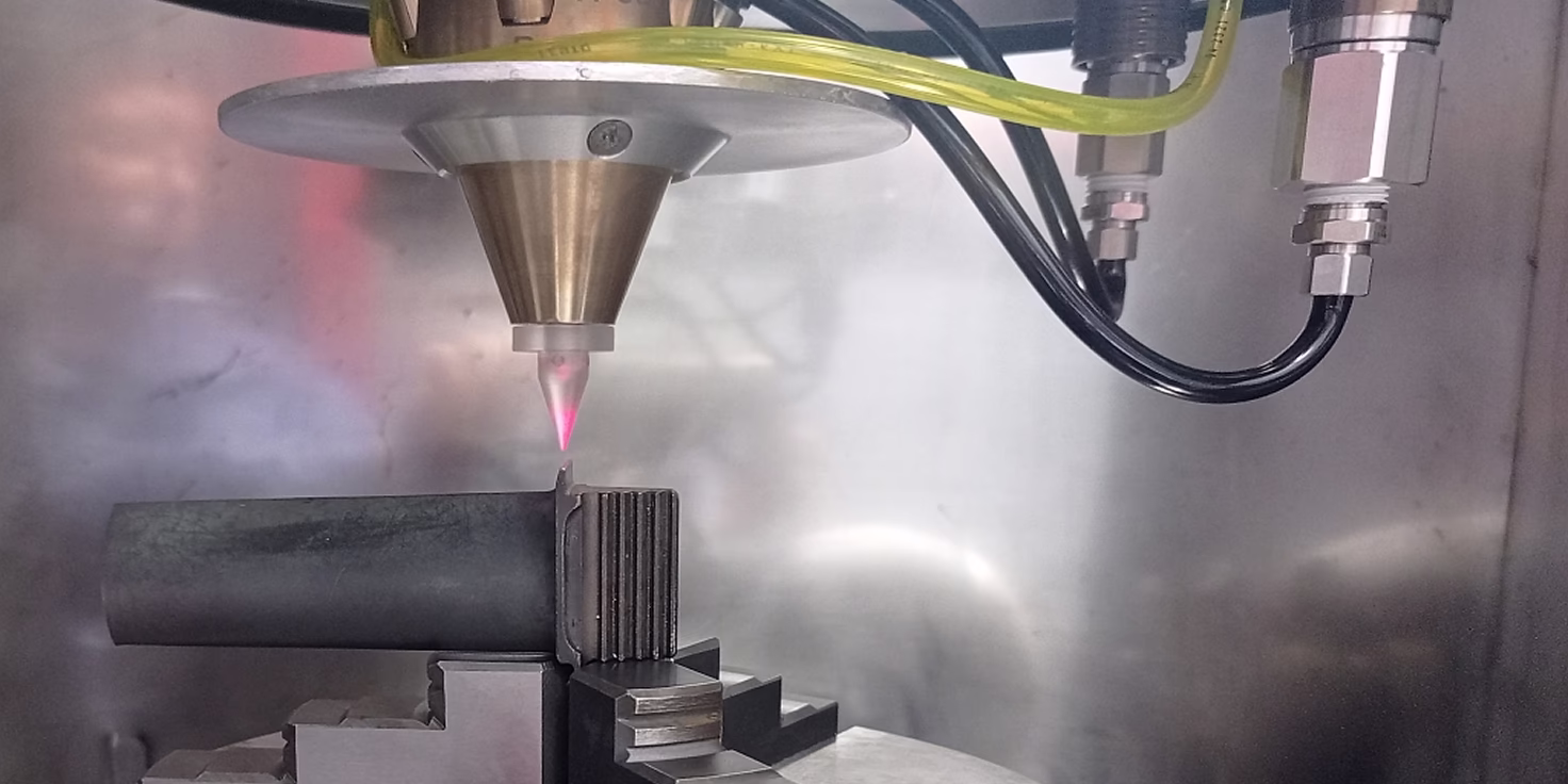
Laser Cladding Process
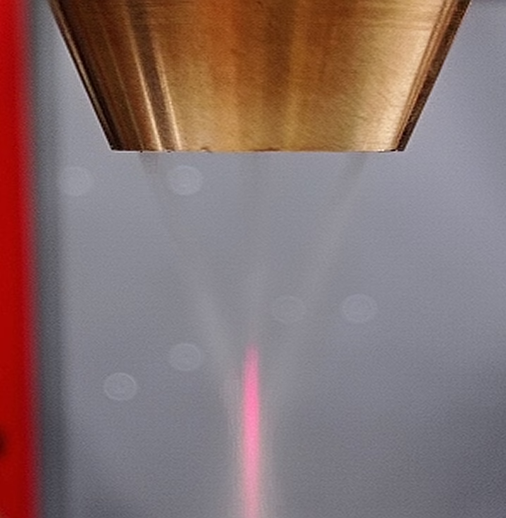
Positioning. Powder and laser beam focusing

Positioning. Working point location on the part
Positioning. Working point location inside controlled atmosphere chamber
Laser cladding process. Technology setup
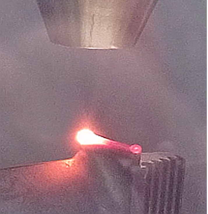
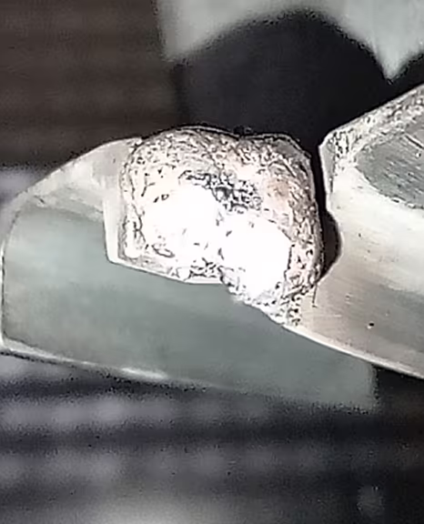
Cladding in controlled atmosphere chamber. Blade tip restoration
Examples of Laser Cladding
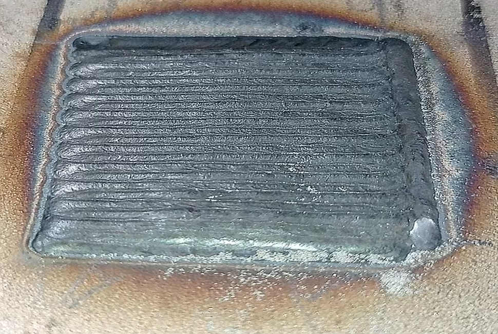

Flat cladding
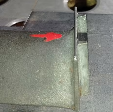
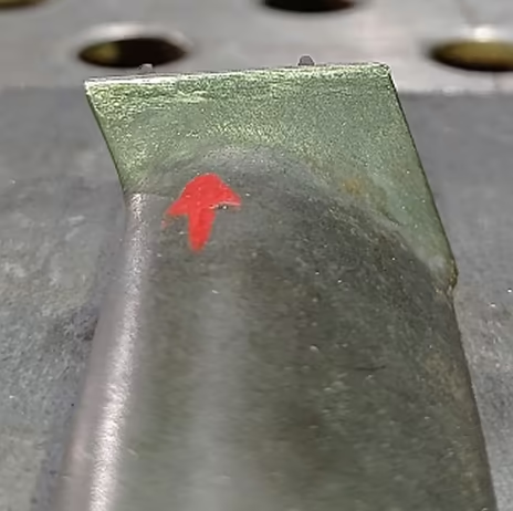
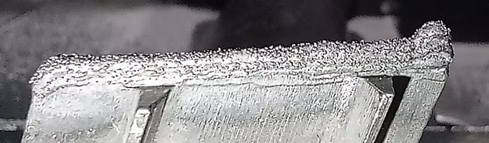
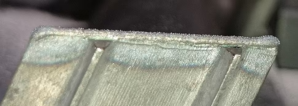
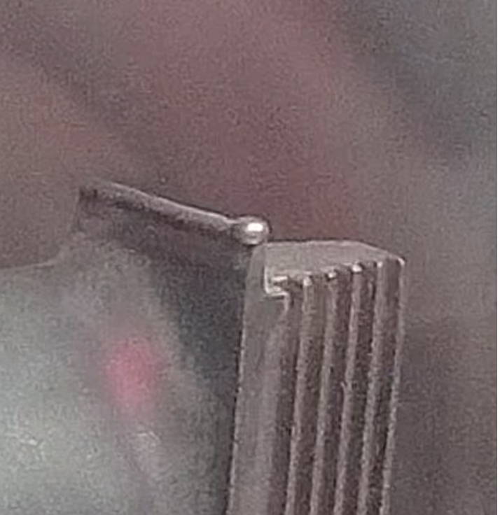
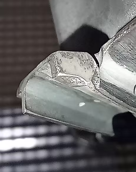
Blade repair. Tip cladding
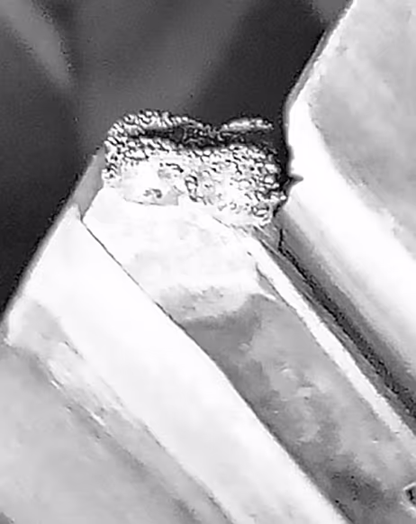
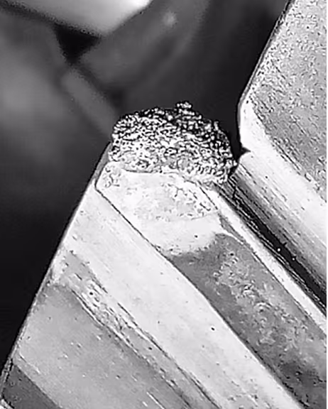
Blade tooth repair with powder cladding
Gallery of completed projects


