Robotic Laser Welding and Cladding Complex
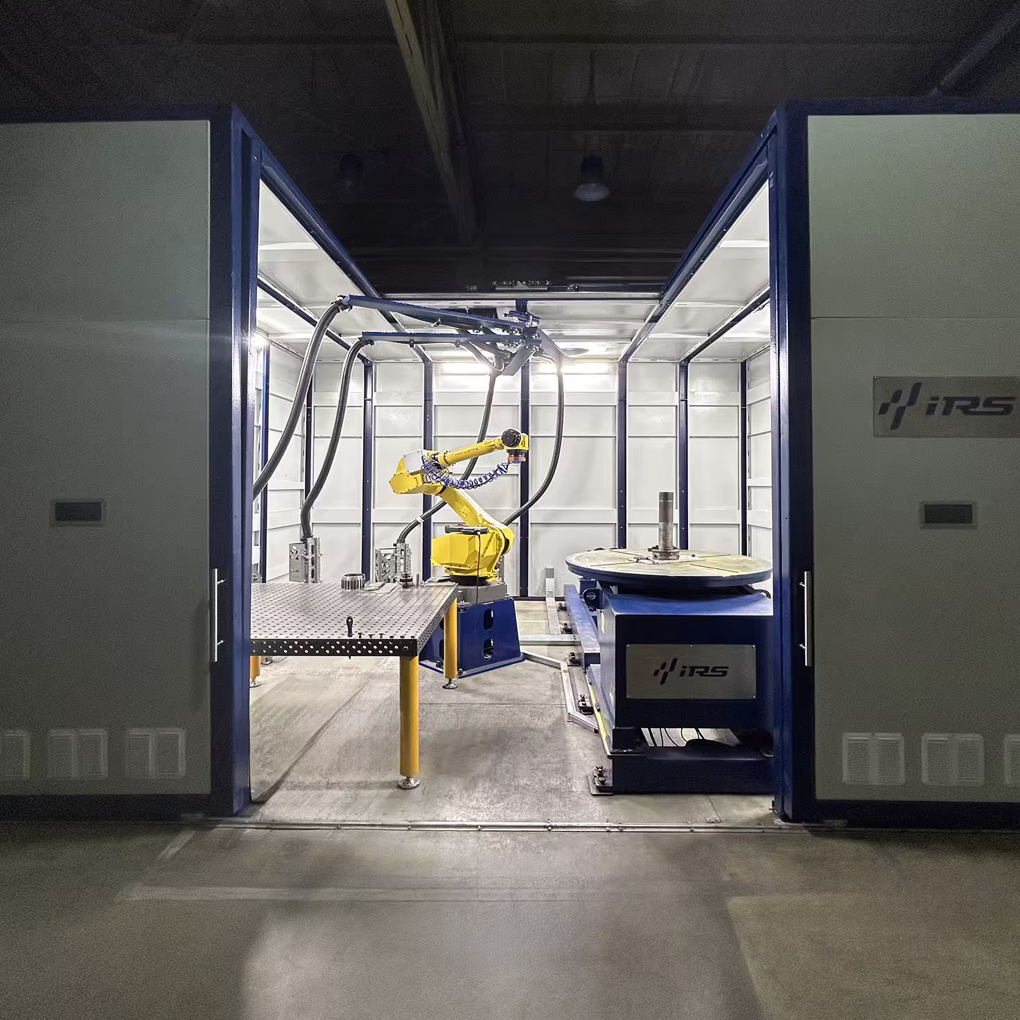
The robotic complex is designed for welding aircraft engine components, cladding parts with alloys to extend the service life of the component, producing parts from special alloys, and plating the internal surfaces of rotating bodies.
The complex enables welding and cladding while eliminating the human factor, handling a large variety of product sizes to achieve maximum productivity, and, compared to other technologies, reducing the time required for post-processing of welds. Additionally, the part manufacturing process allows creating complex geometries from expensive alloys while reducing processing time.
Purpose: specialized, civil, aerospace.
Technical specifications:
Number of laser heads — 4 pcs.
Maximum laser power — 4 kW
Type of laser source — fiber laser
Laser wavelength — 1070 ±10 nm
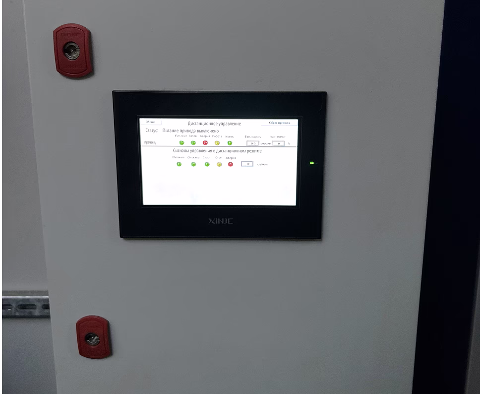
Human-machine interface — graphical control panel with a color HMI touchscreen
Complex control — software on an industrial computer
Video monitoring
Equipment Composition
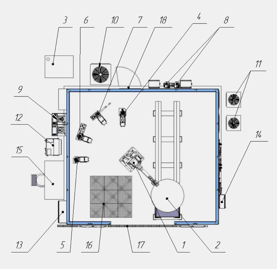
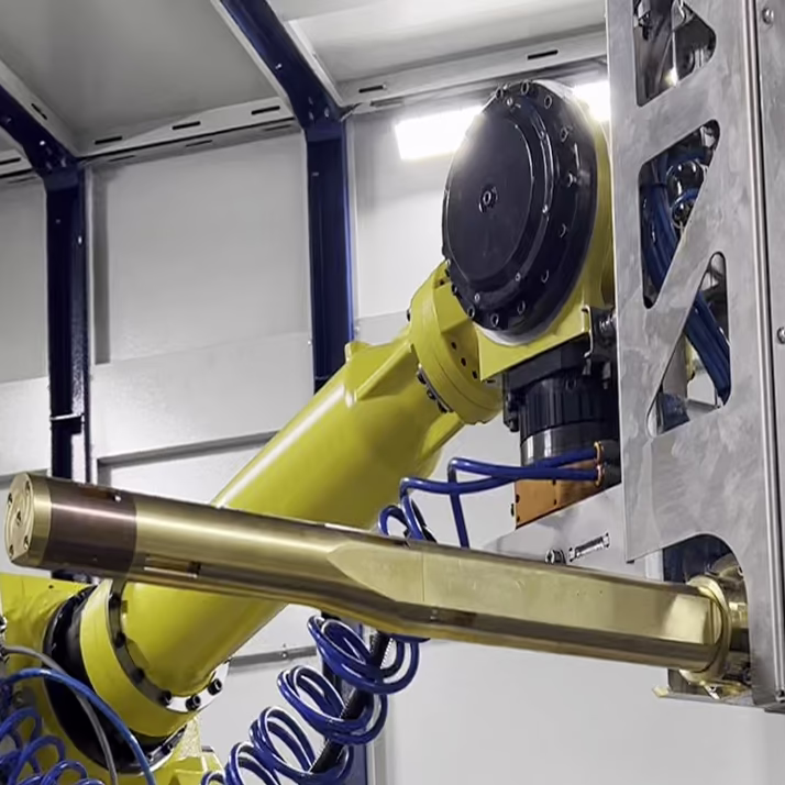
- Industrial manipulator
- Welding 2-axis positioner
- Laser source
- Laser optical head for welding with wire feed
- Laser optical head for powder cladding
- Laser optical head for wire cladding
- Laser optical head for cladding internal surfaces with powder
- Wire feeding mechanism
- Powder feeding system
- Liquid cooling system for laser source
- Liquid cooling system for laser heads
- Industrial robot controller
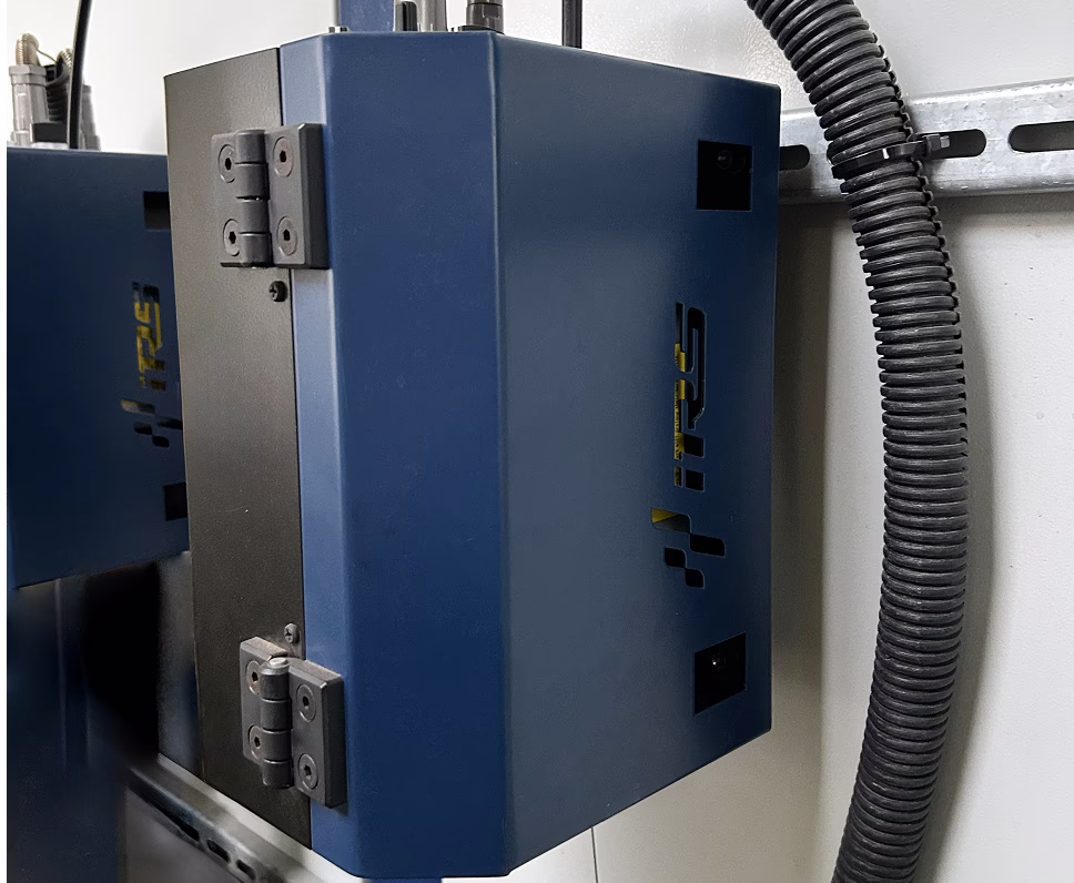
- Complex control cabinet
- Pneumatics control cabinet
- Operator workstation
- Welding table
- Sliding gates
- Access door to the complex
Software Control Capabilities
The control system of the robotic complex is equipped with software for automatic tool selection to simplify the operation of the complex. When programming a trajectory, the operator selects which tool should perform the processing.
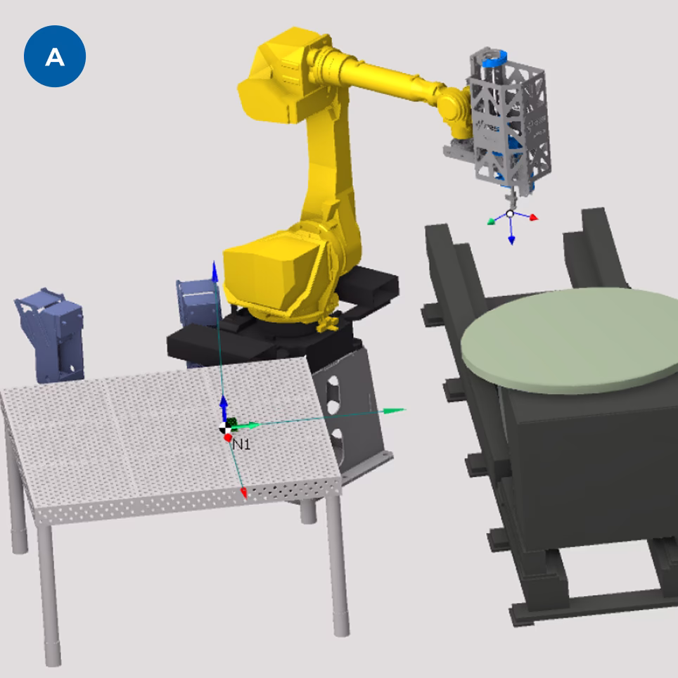
To facilitate the creation of work trajectories, special software is also provided, allowing trajectories to be generated within a virtual model of the complex.
- View of the virtual cell of the complex
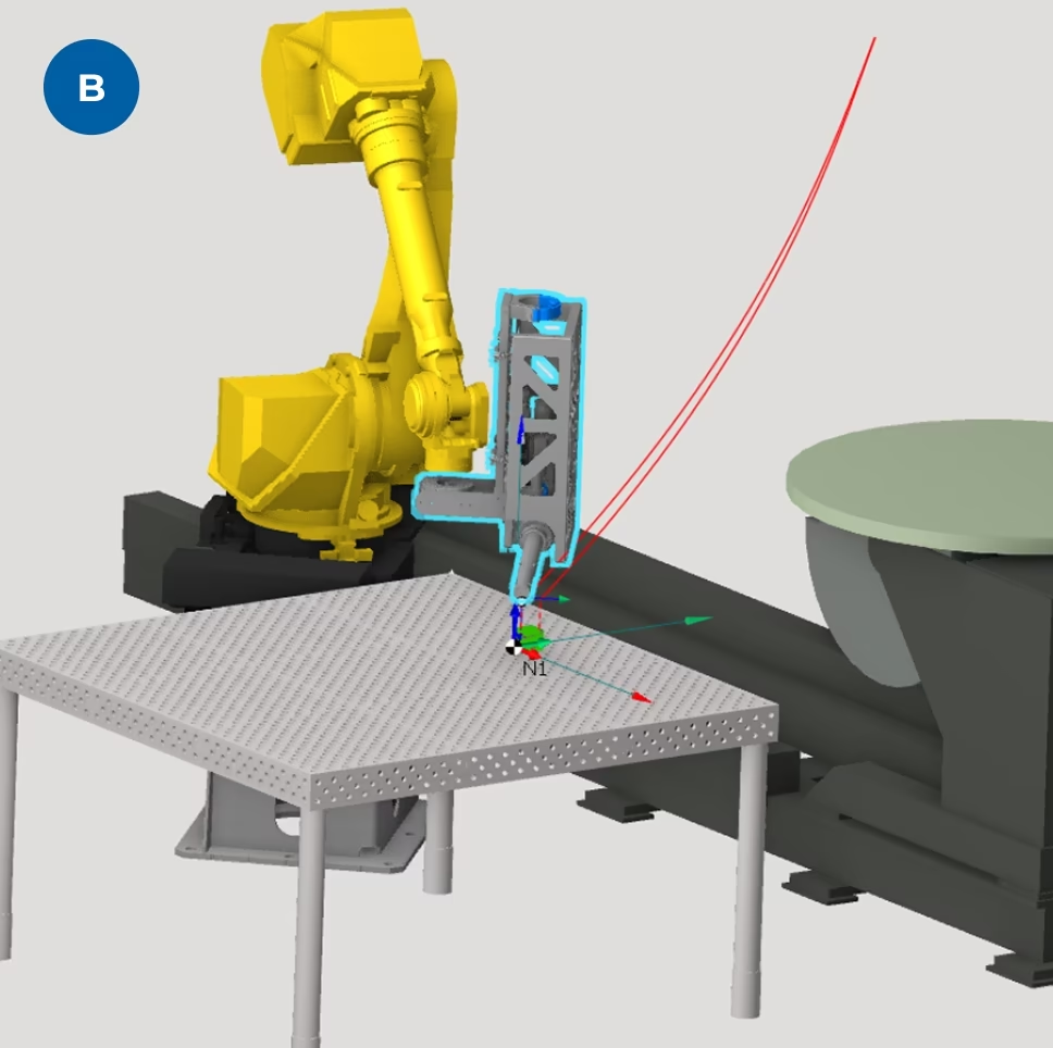
- Example of a programmed trajectory
System Components
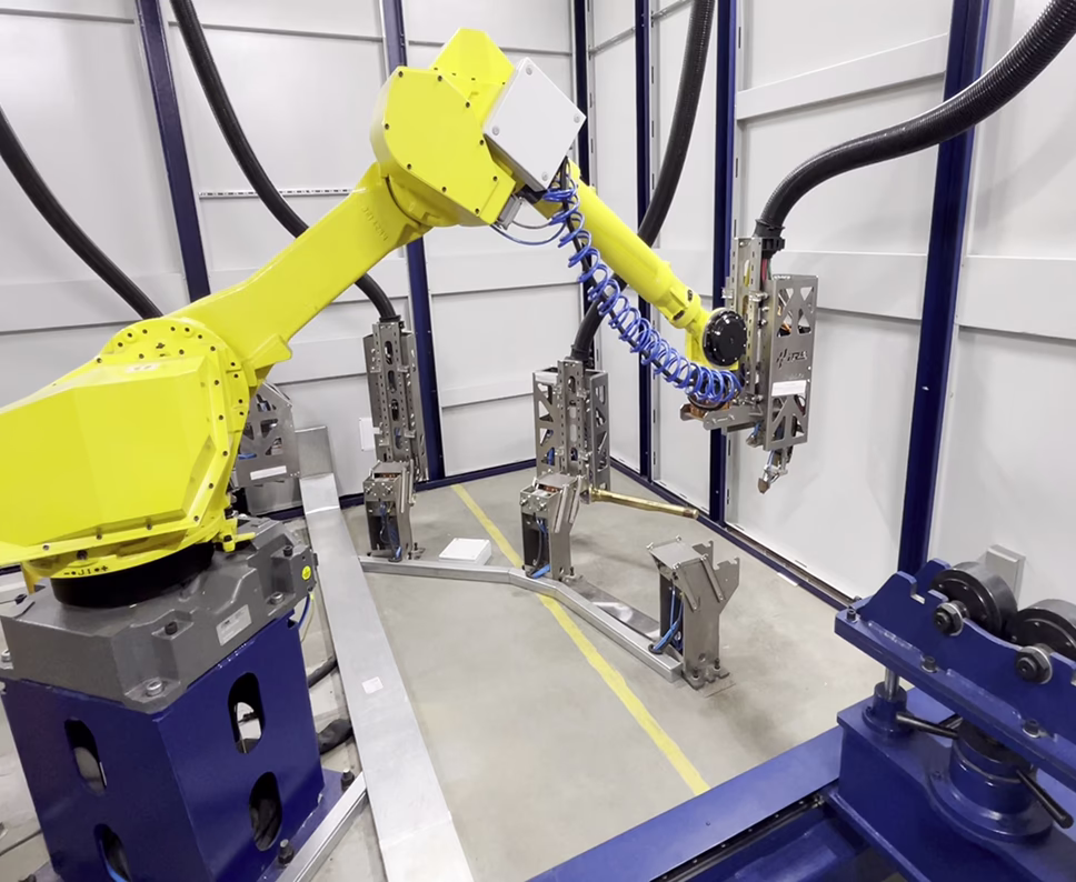
Laser Head Positioning Mechanism
Type of mechanism — industrial robot
Position repeatability stability (ISO9283) — 0.04 mm
Maximum working radius of the robot — 2050 mm
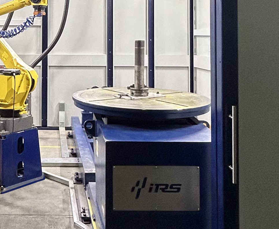
Work Area 1 for Part Processing
Part placement equipment — 2-axis positioner
Position repeatability stability (ISO9283) — 0.1 mm at a radius of 500 mm
Maximum load capacity of the positioner — 1000 kg
Diameter of the positioner's rotary table — 900 mm
Maximum rotation / tilt speed of the table — 6/5 rpm
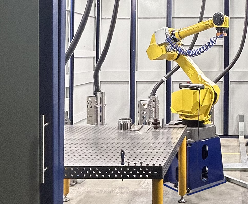
Work Area 2 for Part Processing
Part placement equipment — Welding table, series 16
Dimensions (length × width) — 1500×1500 mm
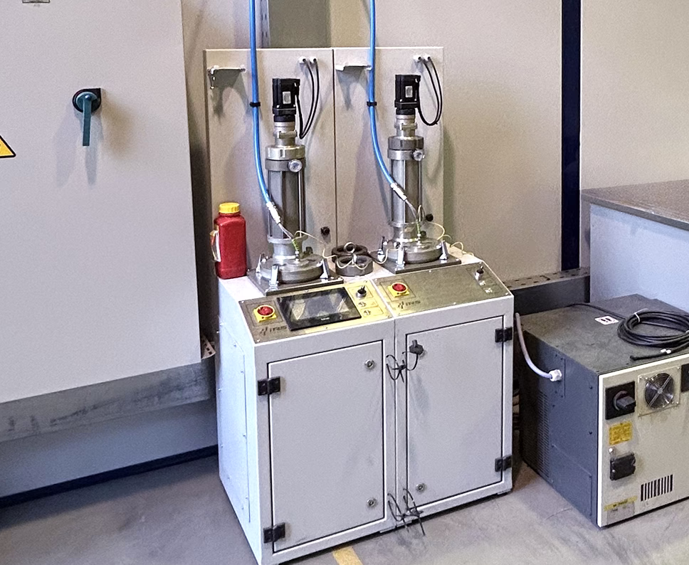
Dual-Chamber IRS Powder Feeder
IRS Wire Feeding Mechanism. Robot Version
IRS Wire Feeding Mechanism. Switching Cabinet with Robot
Laser Heads
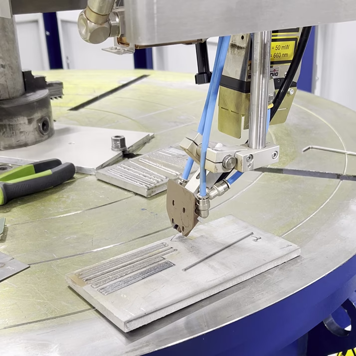
Laser Optical Head for Welding with and without Filler Wire
Maximum power — up to 6 kW
Focal length — 300 mm
Spot diameter at focal length — 0.3 mm
Wire diameter — 0.8–1.6 mm
Nominal feed rate — 0.5–10 m/min
Laser Optical Head for Powder Cladding
Maximum power — up to 8 kW
Focal length — 300 mm
Spot diameter at focal length — 0.8 mm
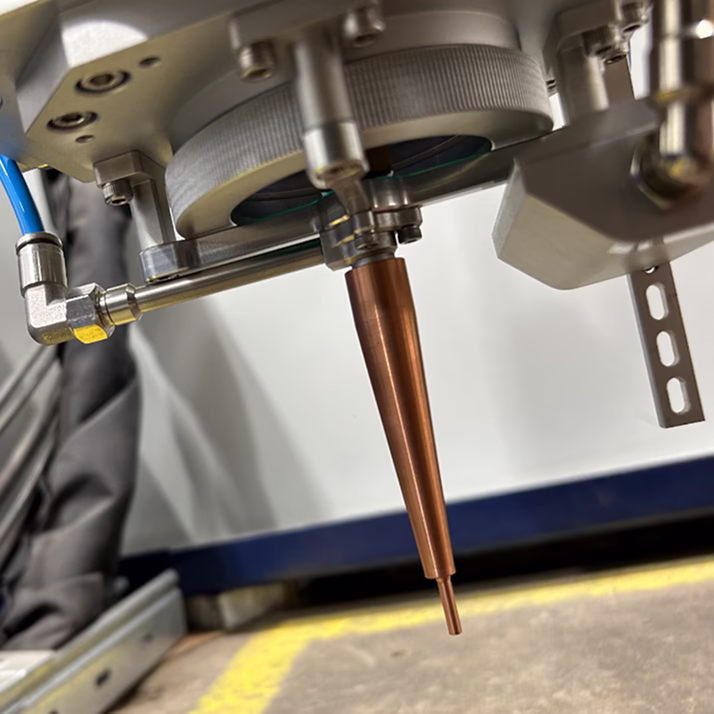
Laser Optical Head for Cladding with Coaxial Filler Wire Feed
Maximum power — up to 6 kW
Focal length — 200 mm
Spot diameter at focal length — 1.75 mm
Wire diameter — 0.8–1.6 mm
Nominal feed rate — 0.5–10 m/min
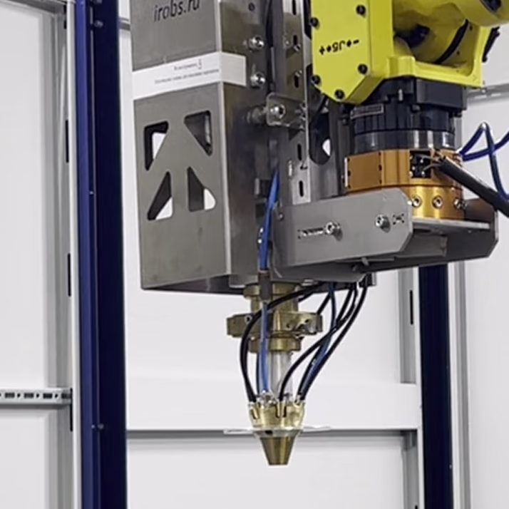
Laser Optical Head for Powder Cladding of Internal Surfaces
Maximum power — up to 4 kW
Working distance — 12–13 mm
Spot diameter at focal length — 2–3 mm
Minimum processing diameter — 60 mm
Maximum processing depth — 500 mm
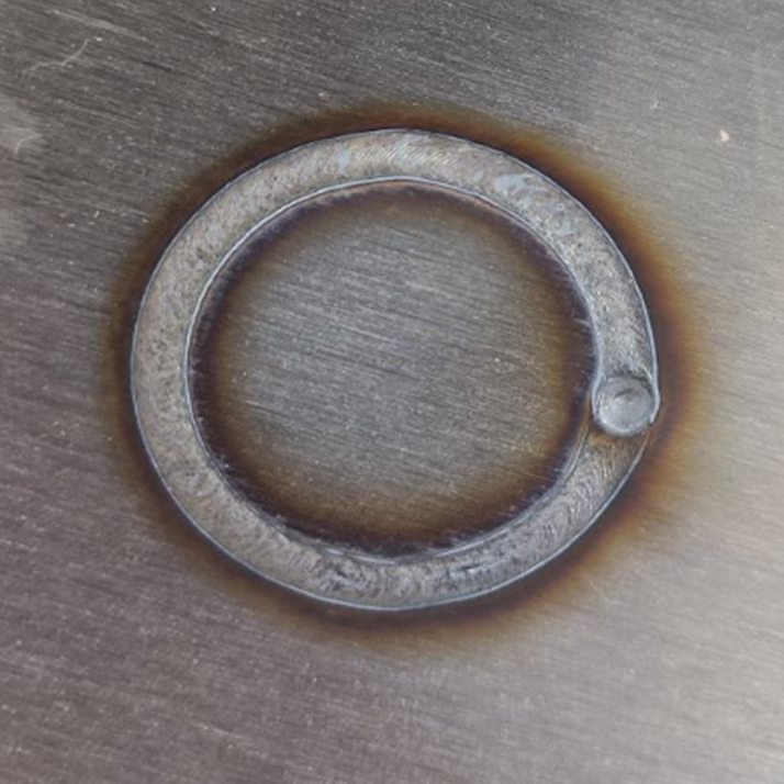
Example of work using laser optical head for welding with and without filler wire
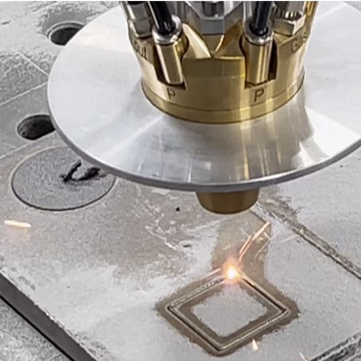
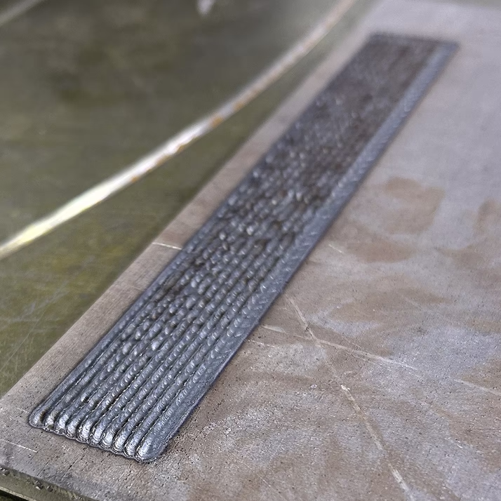
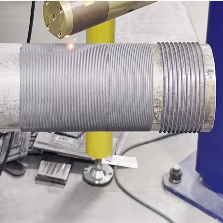
Example of work using laser optical head for powder cladding
Example of work using laser optical head for cladding with coaxial filler wire feed
Example of work using laser optical head for powder cladding of internal surfaces
Gallery of completed projects


