Robotic complex for the production of steel pipelines
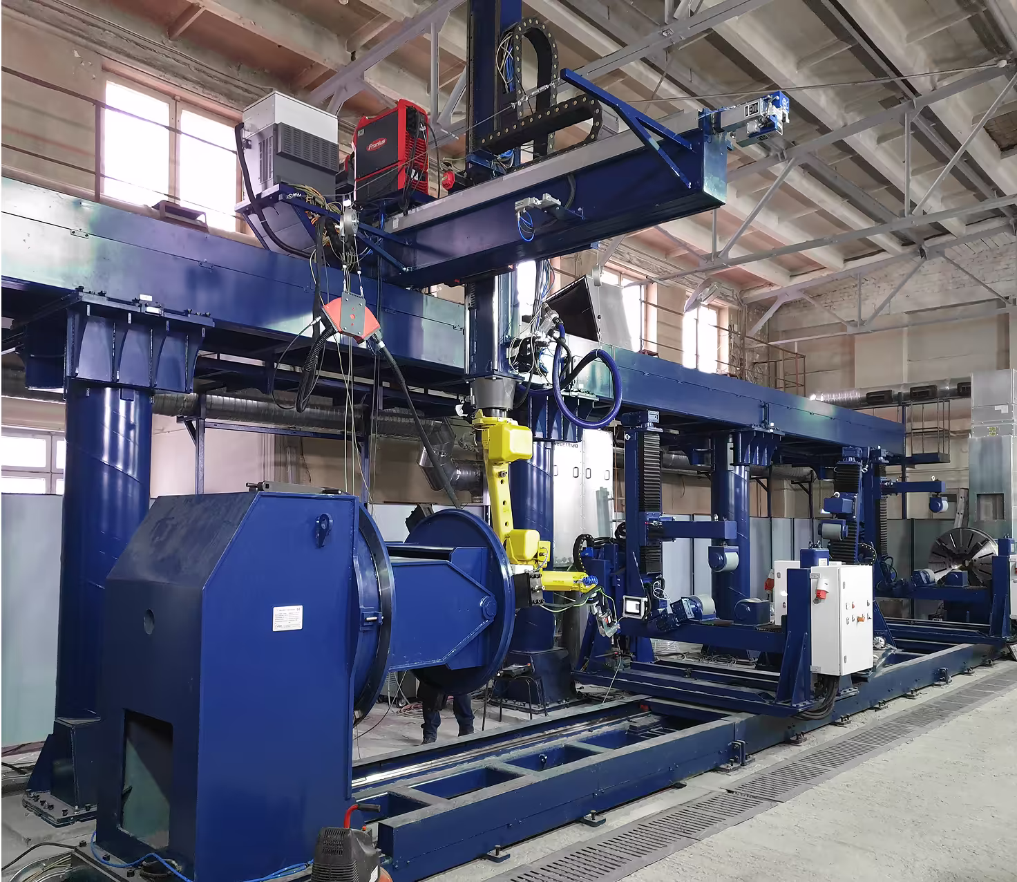
The robotic complex equipment set for the production of steel pipelines is designed for:
- digital 3D scanning of the pipeline work area in the trench;
- model generation and automated cutting of steel components of various shapes, including pipelines for manufacturing tie-in assemblies, tees, and elbows;
- robotic welding of pipeline tie-in assemblies, tees, and elbows.
Brief technical specifications:
Maximum length of the processed part — 10 m
Diameter range of processed parts — 88–1080 mm
Maximum rotation speed of the part — 4.5 rpm
Maximum weight of the processed part — 10 t
Overall repeatability of the complex's tool position — no more than ±0.03 mm
Maximum airflow of the fume extraction system in the tailstock — 5300 m³/h
Maximum airflow of the general shop fume extraction system — 10600 m³/h
Air purification efficiency — 99.9%
Equipment Composition
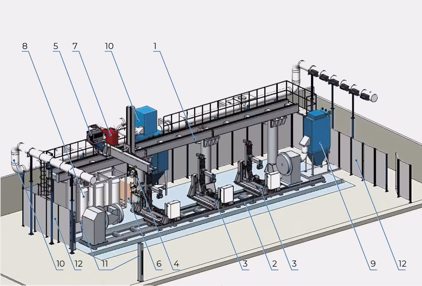
- Three-axis robot movement gantry iRS 3 Axe Weld Gantry 1520
- Single-axis welding positioner iRS 1 Axe Lathe 5000-10 with horizontal rotation axis, load capacity 5000 kg
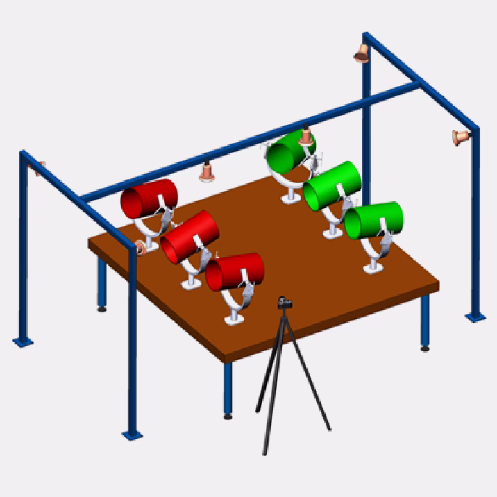
- Set of specialized iRS RO-4 axe supports for the single-axis positioner (enabling the positioning of cut pipe sections in various orientations)
- Industrial robot
- Controller with IRS complex control cabinet
- Plasma cutting equipment with a fully automatic gas console and digital CNC control
- Welding equipment based on a welding power source
- Gas supply system for the plasma cutting source using high-purity technical gases (nitrogen, argon, oxygen)
- Fume extraction system from the idle headstock of the positioner
- General shop Push-Pull fume extraction system
- Laser safety system
- iRS metal safety enclosure
General Operating Principles of the Complex
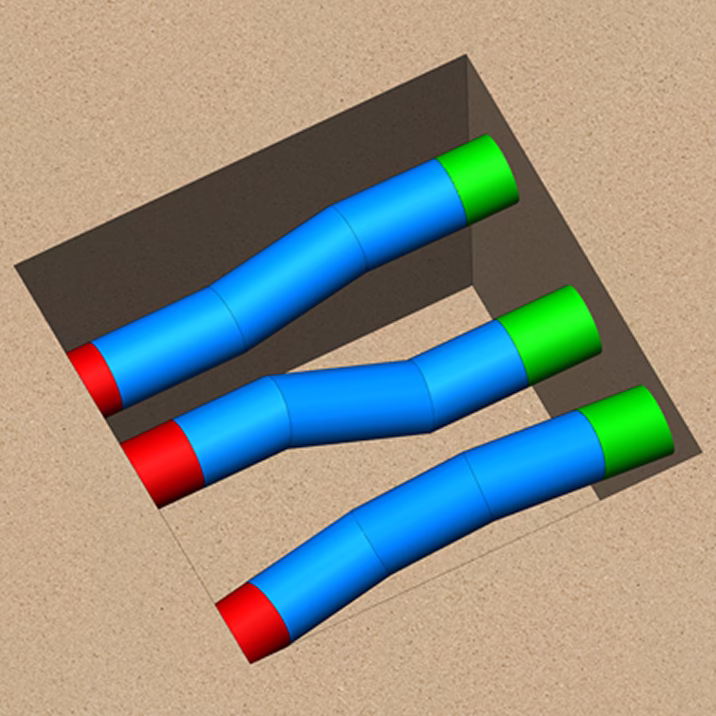
Digital 3D scanning of the pipeline work area in a trench or laboratory
Transmitting the acquired data over the Internet to production. The designer receives digital data on the actual position of pipeline ends
Determining the configuration of connection joints
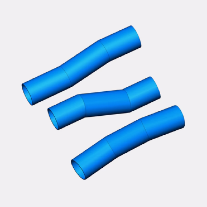
Modeling of connection joints
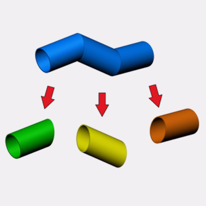
Breaking down connection joints into individual components
Creating a control program for the robotic pipe cutting complex used in joint assembly
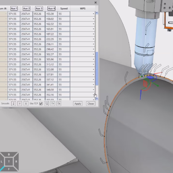
Uploading the cutting control program to the robotic complex
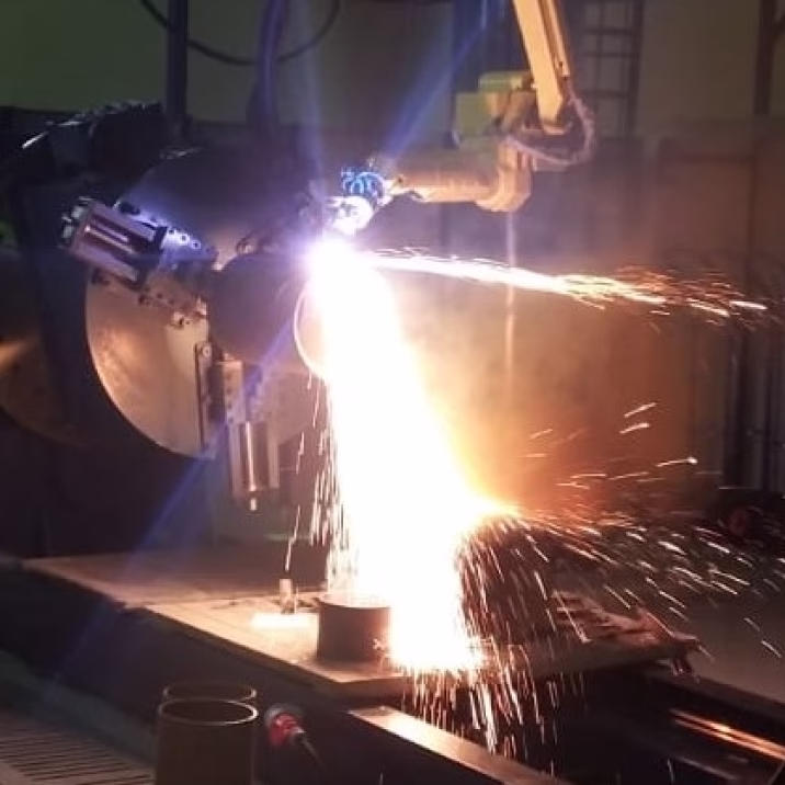
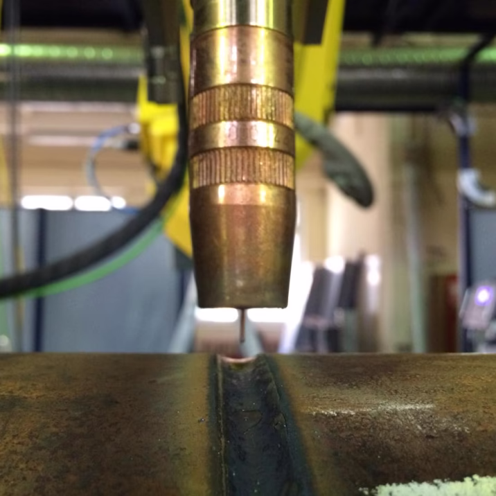
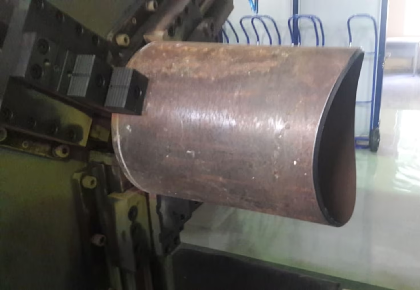
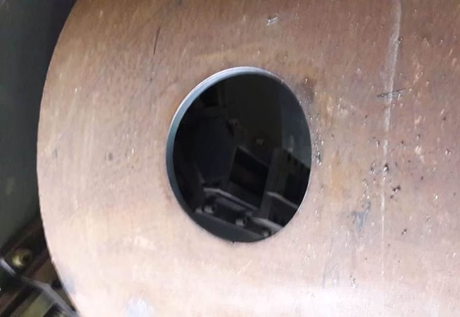
Plasma cutting of components on the robotic complex
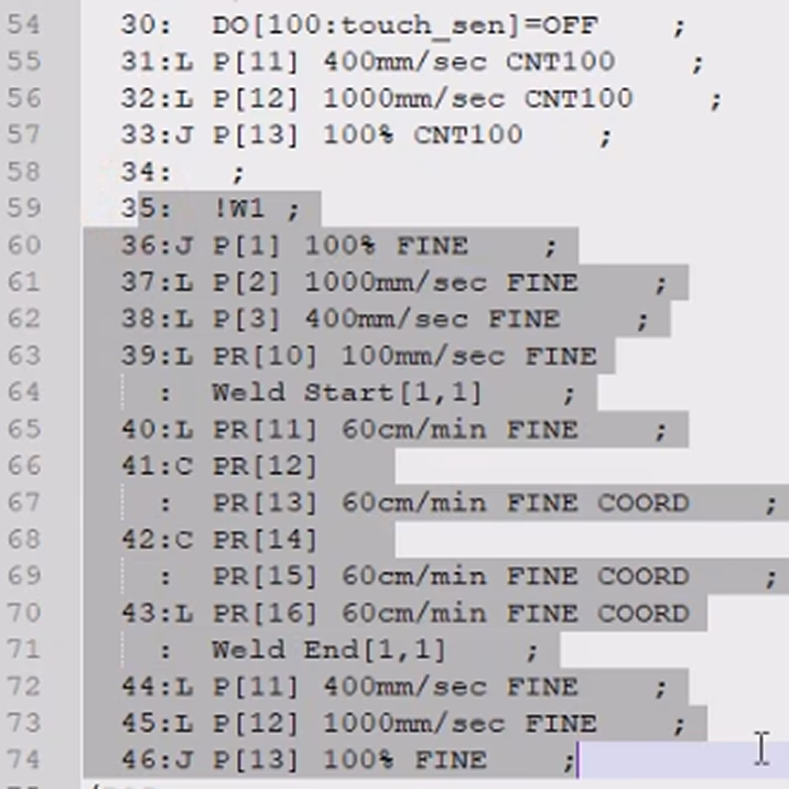
Creating and uploading the welding control program for the robotic complex assembling the pipe joints
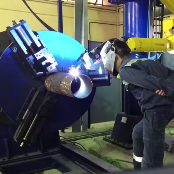
MIG/MAG welding of pipes used in the assembly of connection joints on the robotic complex
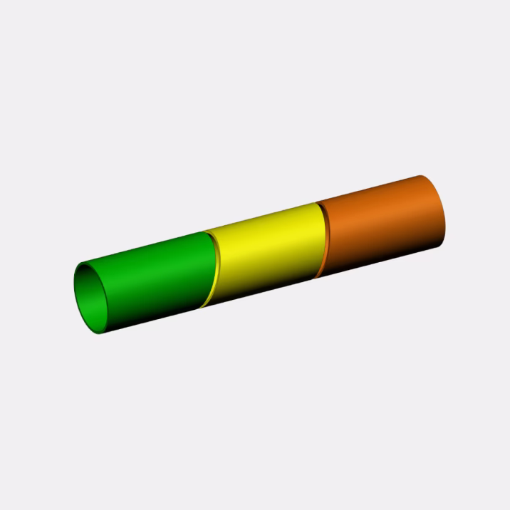
Results of welding seams of the connection joint
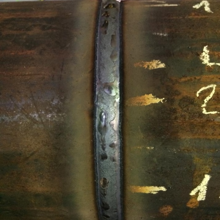
Final results of welding seams of the connection joint
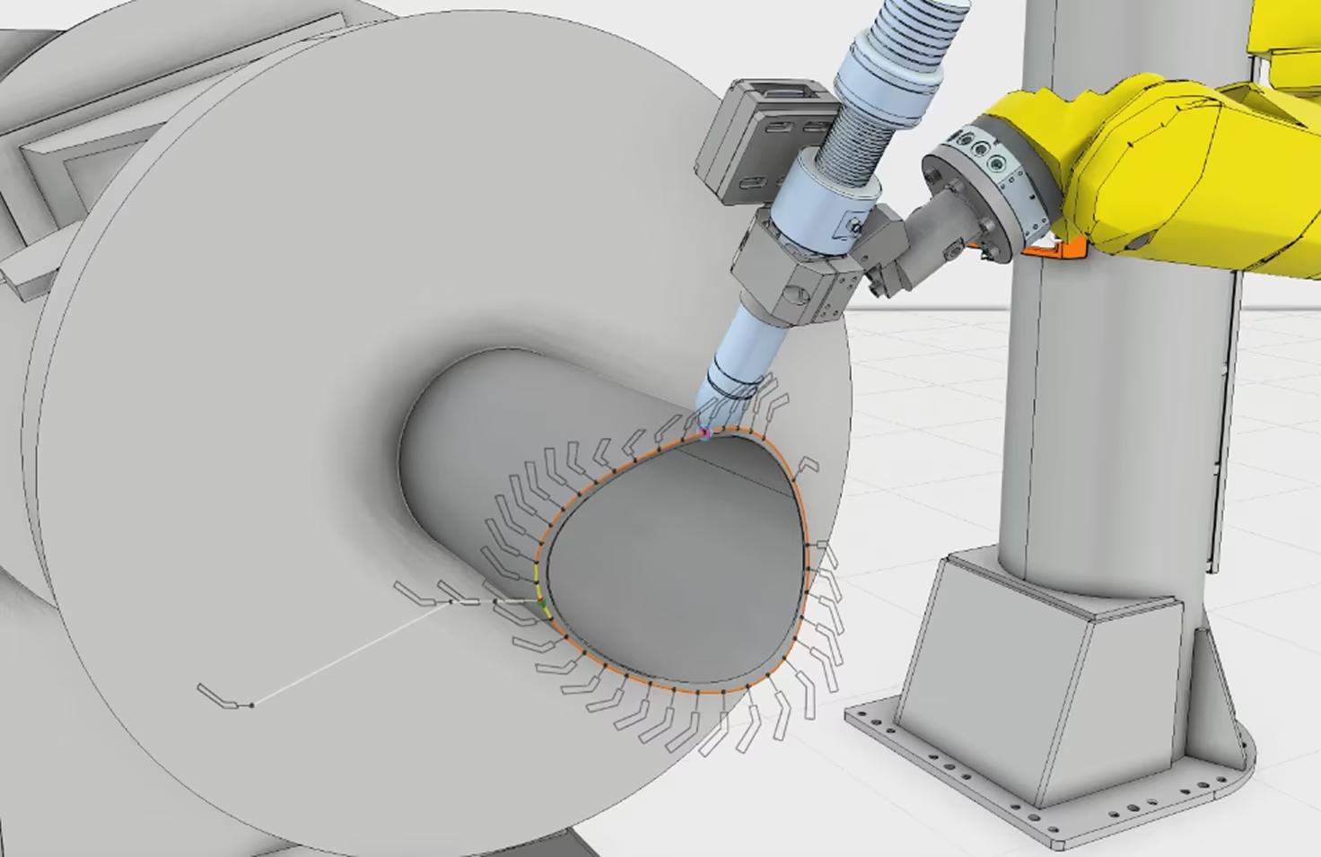
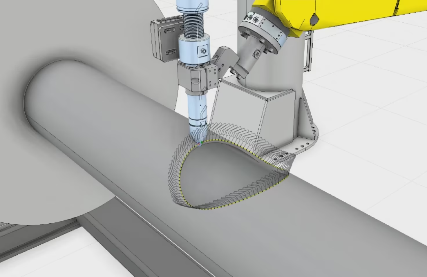
Plasma Cutting of an Elbow Assembly
Examples of the Complex in Operation
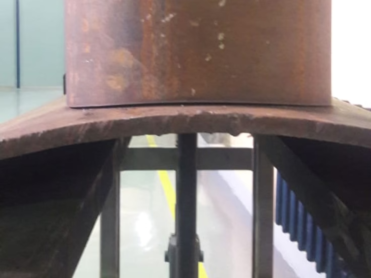
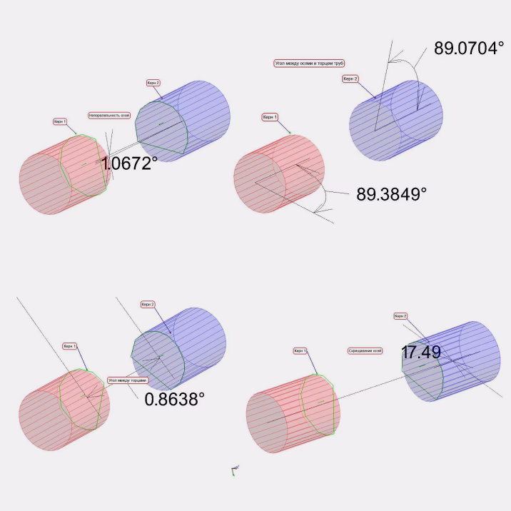
High-precision assembly of an elbow
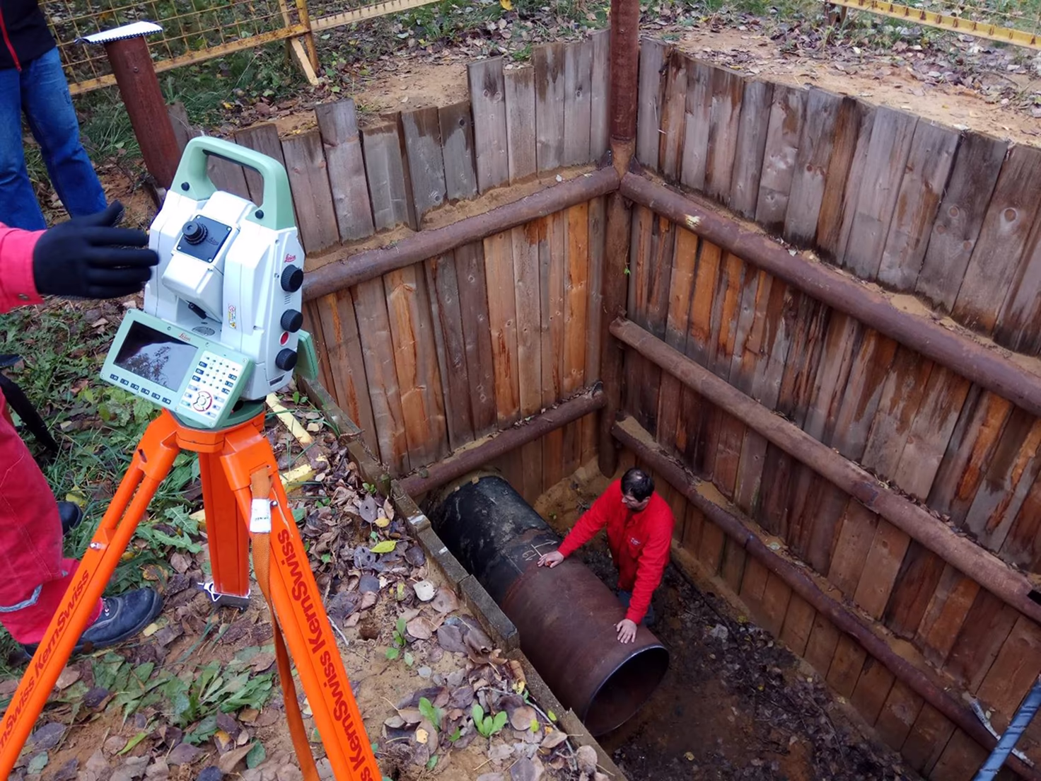
Digital 3D scanning of a pipeline section in a trench
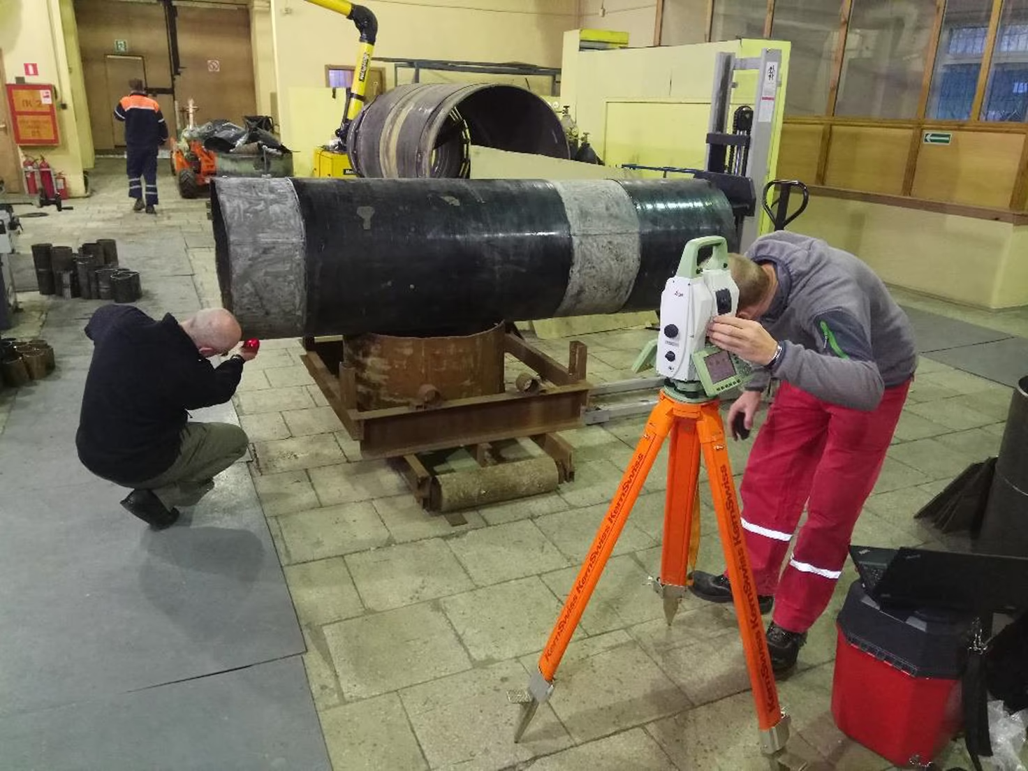
Digital 3D scanning of a pipeline section under laboratory conditions
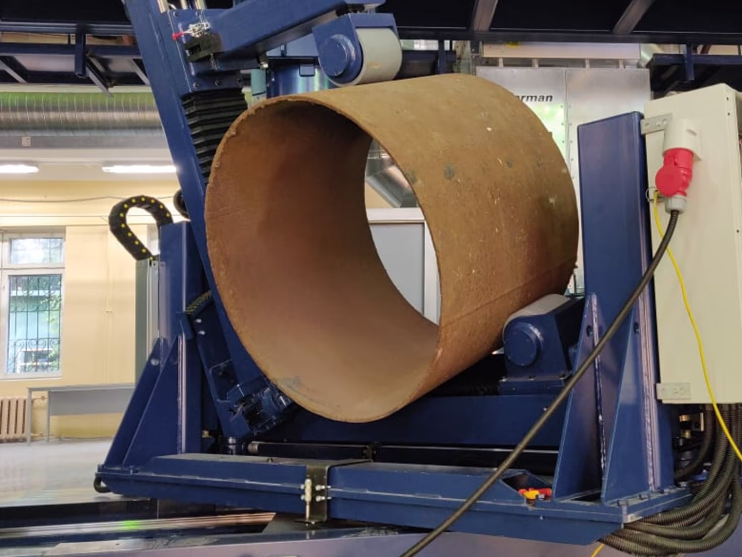
Tilting a part in a roller support
Gallery of completed projects


