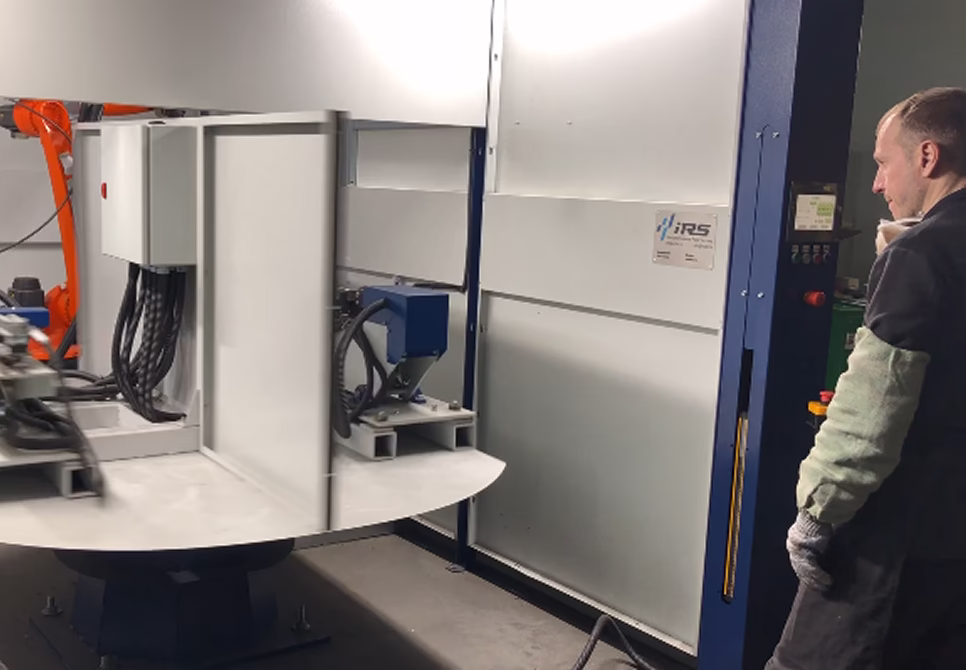
Robotic complex for MIG/MAG welding of shock absorber rods and housings
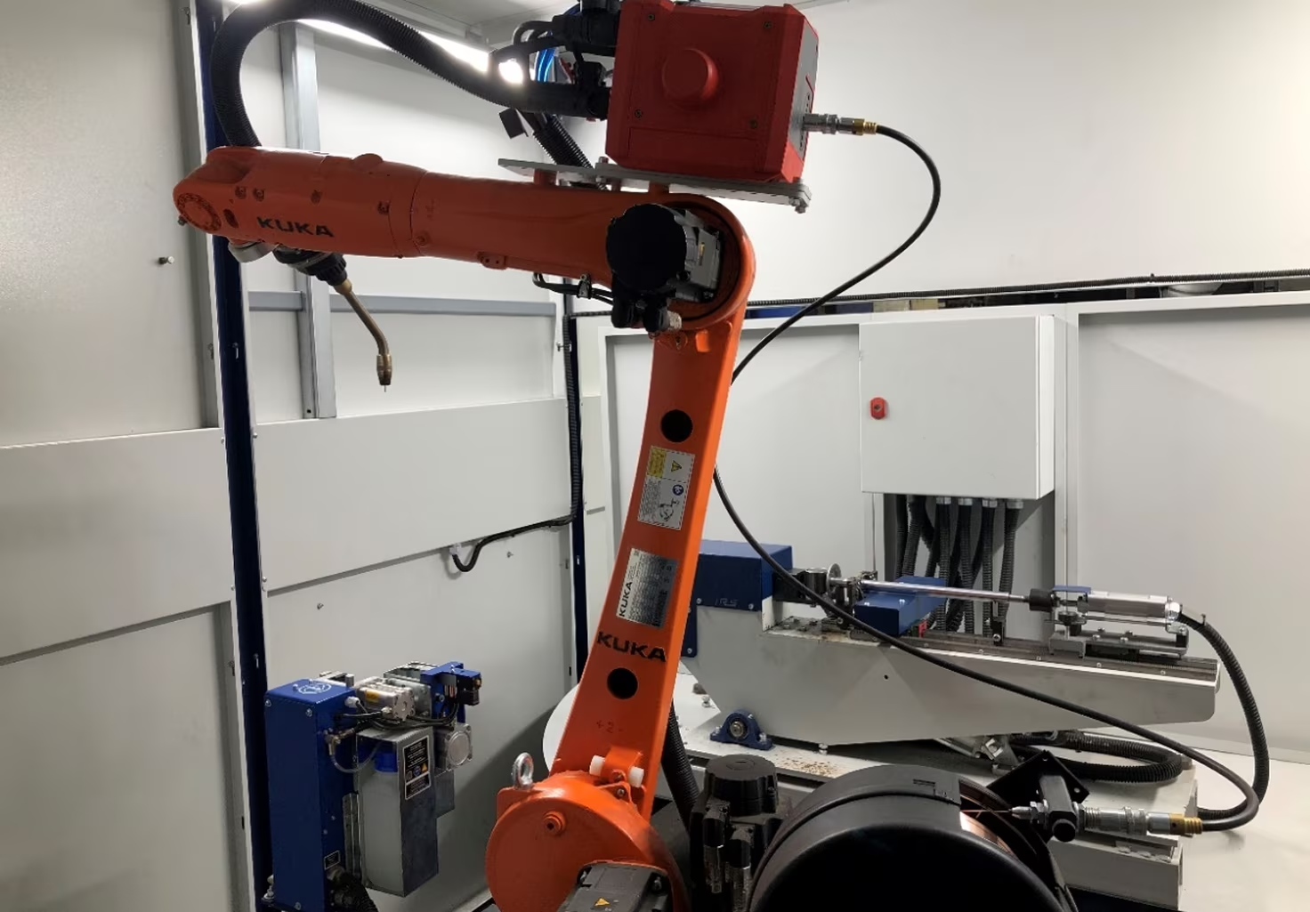
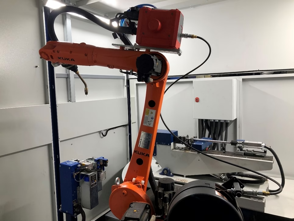
The robotic complex is designed to perform technological welding operations on shock absorber rods and housings. The complex includes two workstations, each consisting of an industrial manipulator with a welding equipment set, a positioner, and a set of assembly-welding fixtures. The parts to be processed are placed on the workstations manually, and fixation is achieved using pneumatic clamps controlled by the operator's pedal. Two sets of fixtures mounted on the positioner ensure a continuous production process: while one set of fixtures is in the welding operation zone, the other is in the assembly zone preparing the next parts for welding. The positioner rotation is controlled using a button on the front control panel of the complex.
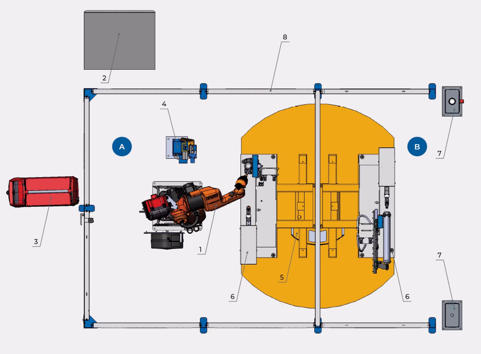
Workstation Layout
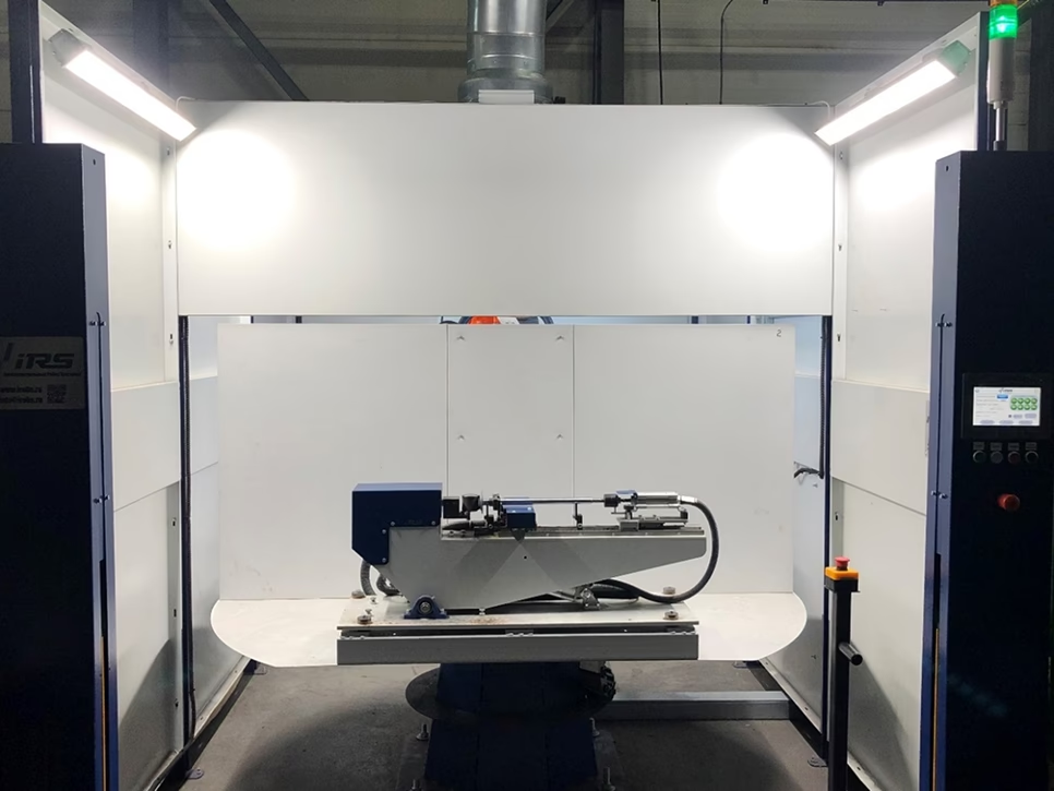
Welding Zone
Operator Zone
Equipment Components
- Industrial manipulator
- Industrial manipulator controller
- Welding power source
- Welding torch cleaning station
- Single-axis positioner
- Two sets of assembly-welding fixtures
- Stands with protective light barriers and operator panel
- Protective enclosure
Not shown in the diagram
- Robotic complex control cabinet
- Servo drive control cabinet
- Fume extraction system
- Operator foot pedal
Work Zones
A — Welding zone
B — Operator zone
Both workstations are structurally identical. The difference lies in the fixture sets mounted on the positioners.
A single operator can service one workstation.
Programming and adjustment of work routines are carried out using the industrial manipulator training console, while program execution in automatic mode is performed from the operator control panel located on the loading/unloading side of the workstation.
System Components
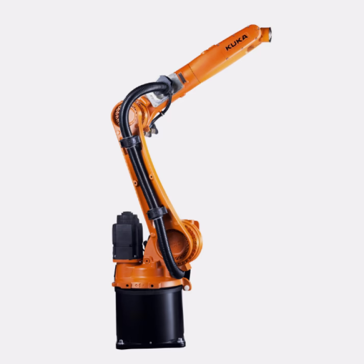
Industrial Manipulator
Type — articulated anthropomorphic
Max. working radius — 1620 mm
Rated payload — 8 kg
Position repeatability (ISO 9283) — ± 0.04 mm
Number of axes — 6
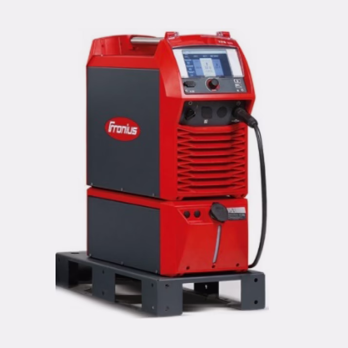
Welding Power Source
Welding torch cooling — liquid
Current range — 3–400 A
Duty cycle at 10 min / 40°C: 40% — 400 A; 60% — 360 A; 100% — 320 A
Output voltage range (MIG/MAG) — 14.2–34.0 V
Efficiency at 400 A / 36 V — 89%
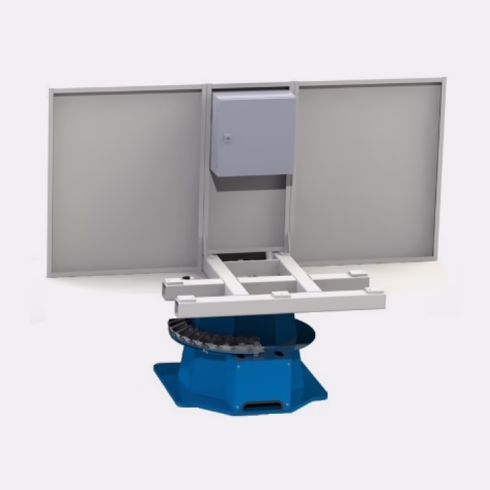
Positioner IRS.080-3.00.000
Number of axes — 1
Max. payload — 500 kg
Max. torque — 470 N·m
Repeatability — ± 0.02 mm
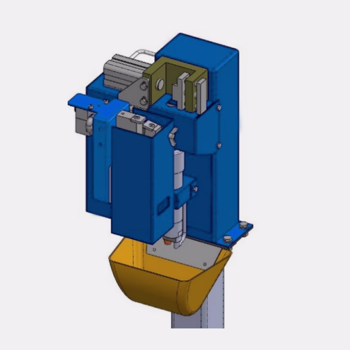
Welding Torch Cleaning Station
Wire cutting module time — 2–3 s
Nozzle cleaning module time — 3–4 s
Liquid injection module time — 2–3 s
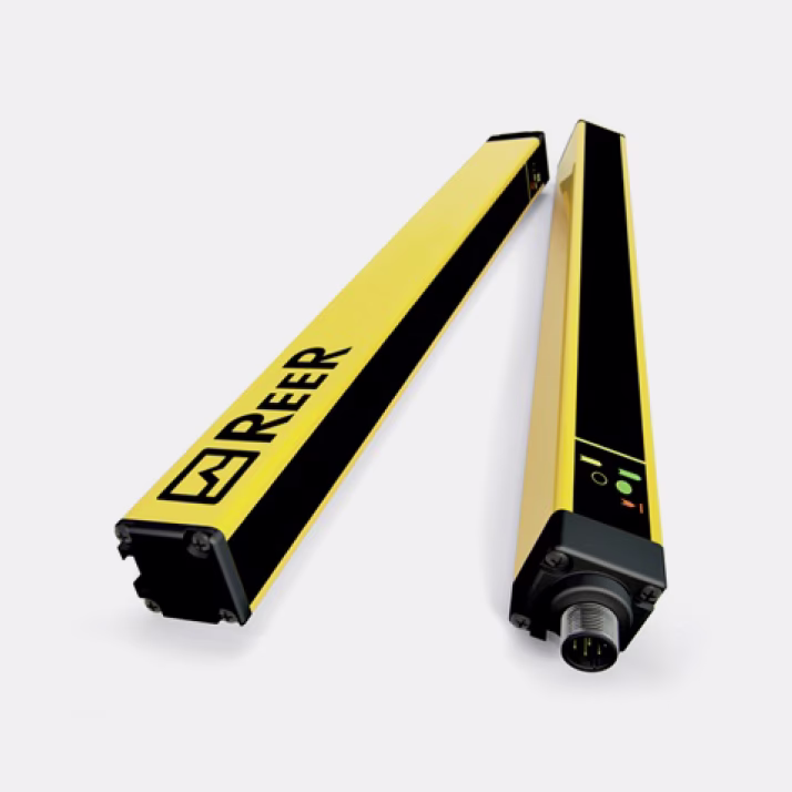
Protective Light Barriers
Number of beams — 2
Response time — 2.5 ms
Protected height — 500 mm
Total curtain height — 510 mm
Max. distance between receivers — 12 m
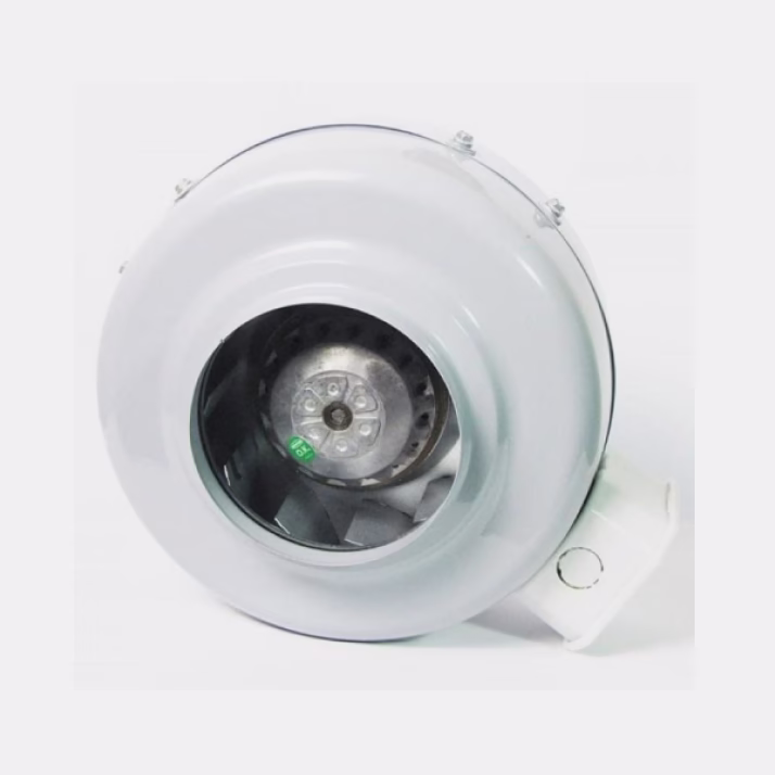
Fume Extraction System
Power — 210 W
Airflow — 1750 m³/h
Dimensions (W×D×H) — 400×400×285 mm
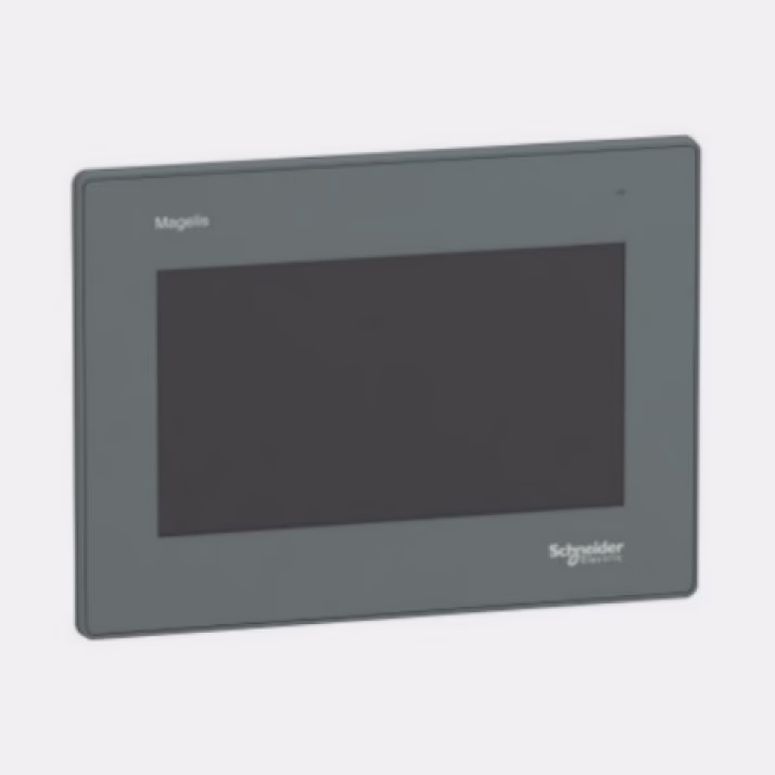
Operator Graphical Panel
Screen size — 7 inches
Panel type — touch
Welding Technology
Shock Absorber Rod Welding
Welding of the lug ends to the housing cover, seam 1
Welding of the housing cover to the rod, seam 2
Final welding of the lug to the housing cover, seam 3
Shock Absorber Housing Welding
Welding the lug ends to the housing bottom, seam 1
Welding the housing to the bottom, seam 2
Final welding of the lug to the housing bottom, seam 3
Operator Workflow Algorithm
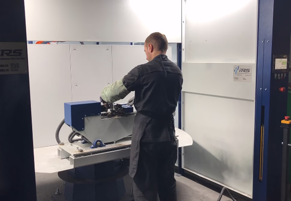
Placing parts
Securing parts using operator pedal
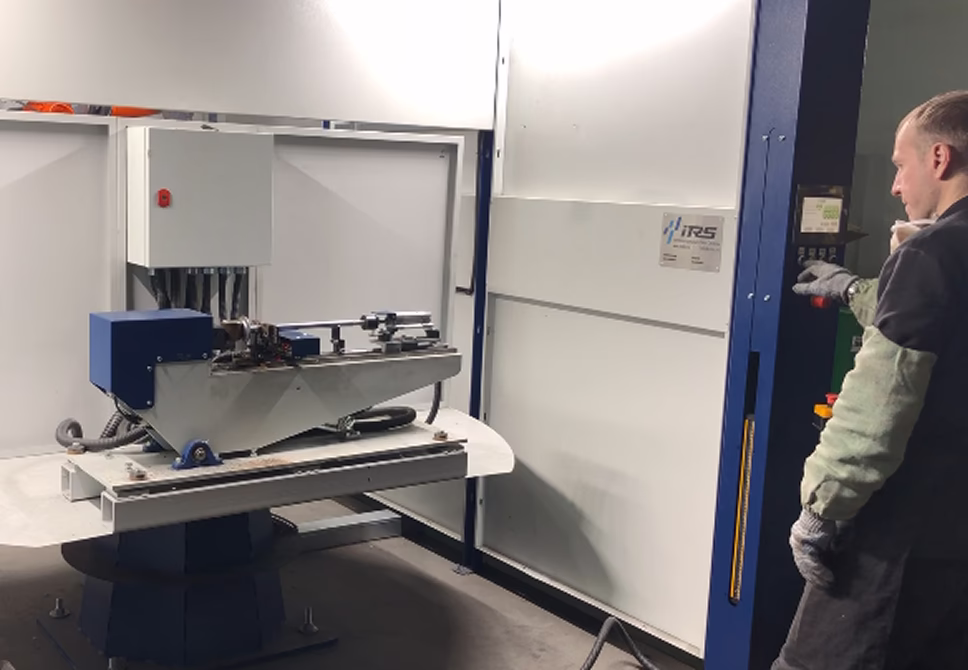
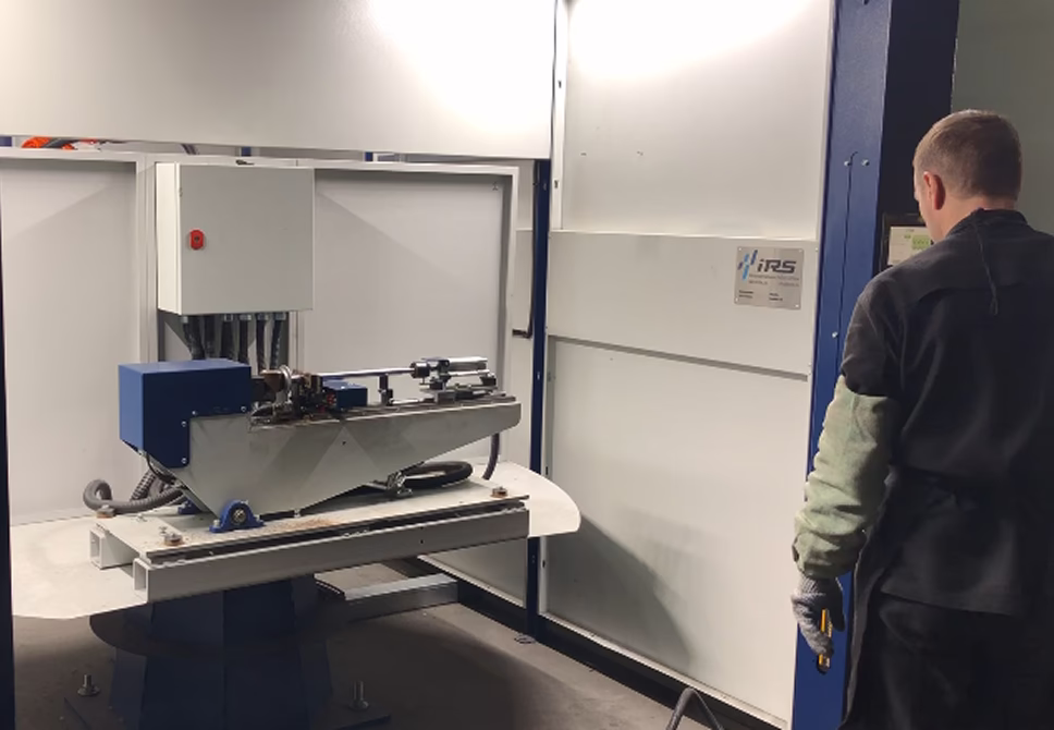
Starting welding cycle from control panel
Beginning of welding cycle: turning the positioner
Releasing finished part using operator pedal
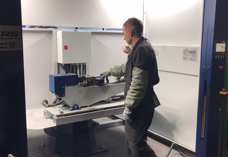
Removing finished part and placing next parts for welding
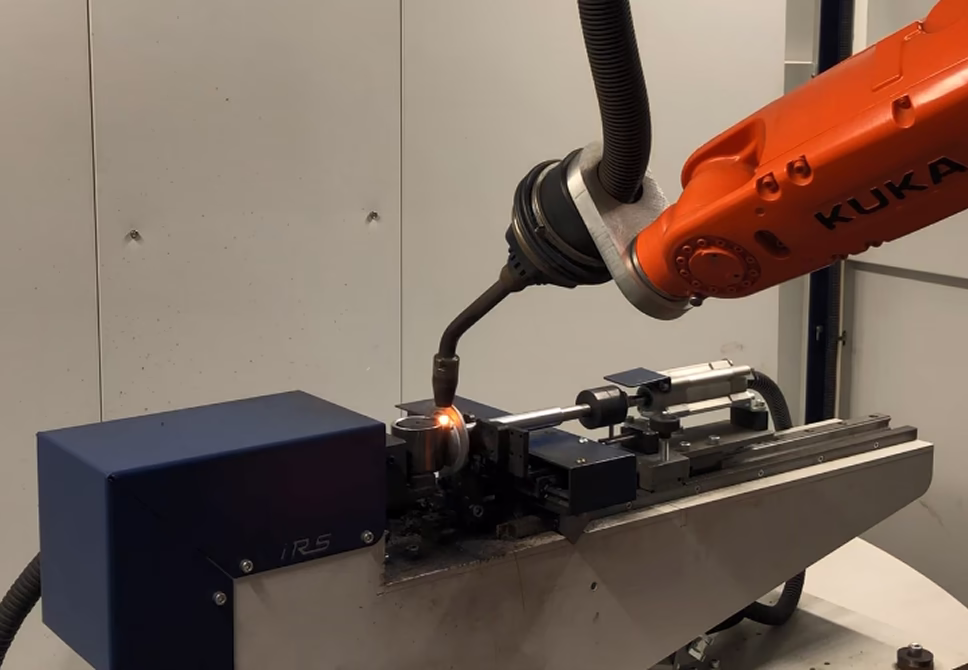
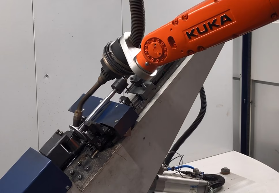
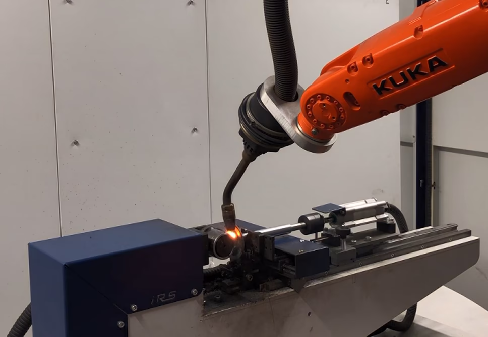
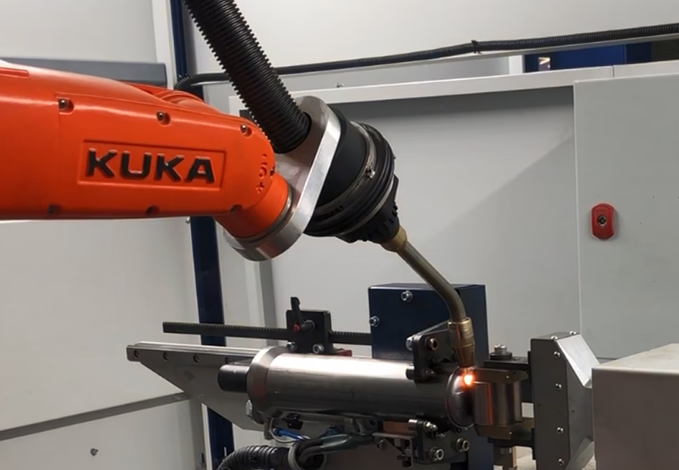
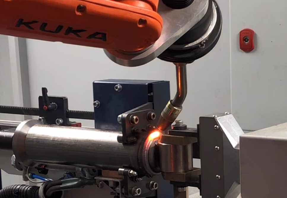
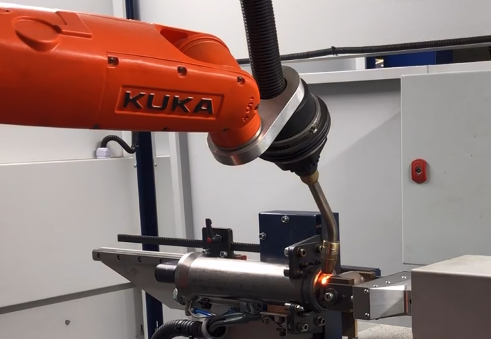
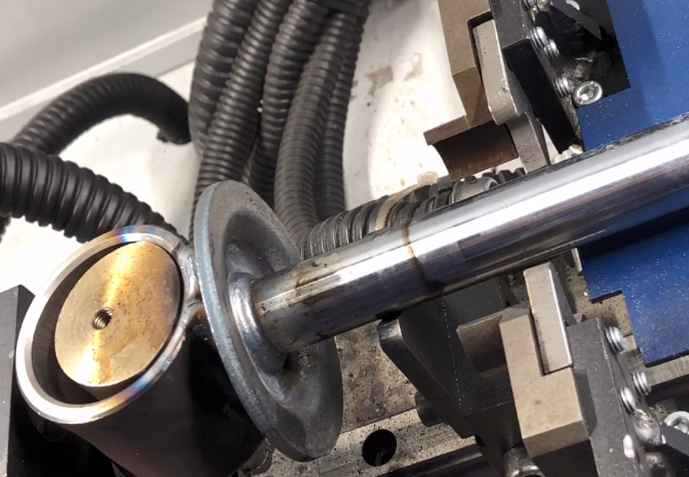
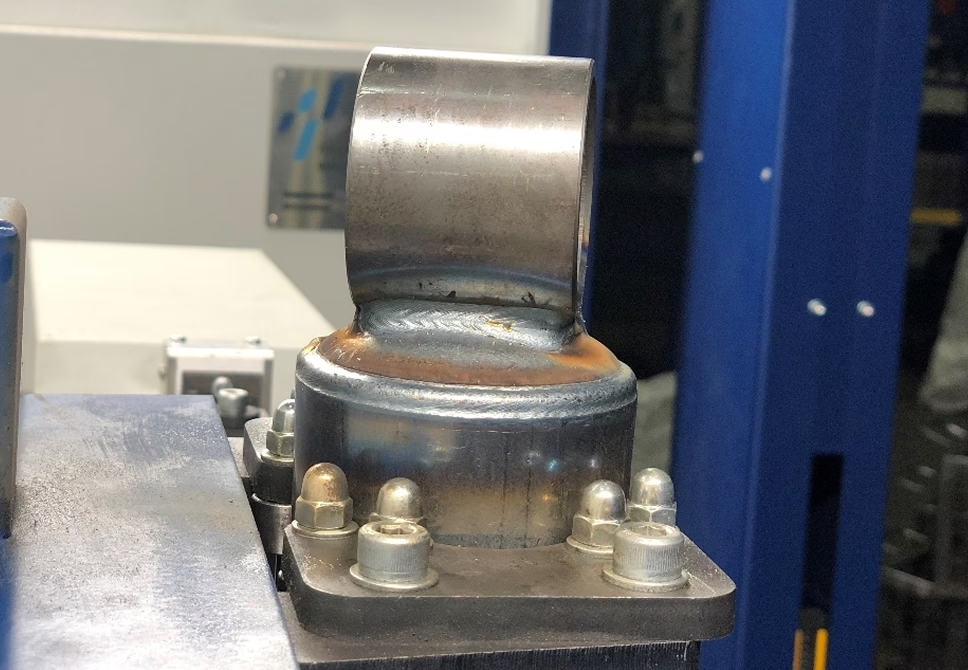
Examples of Complex Operation
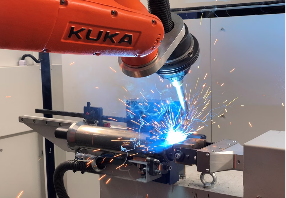
Welding process of the shock absorber body
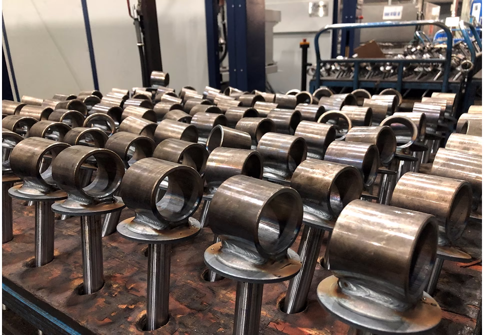
Finished products
Shock absorber body after welding
Gallery of completed projects


