Robotic complex for MIG/MAG welding of electrical cabinets
Robotic Complex for MIG/MAG Welding of Electrical Cabinets
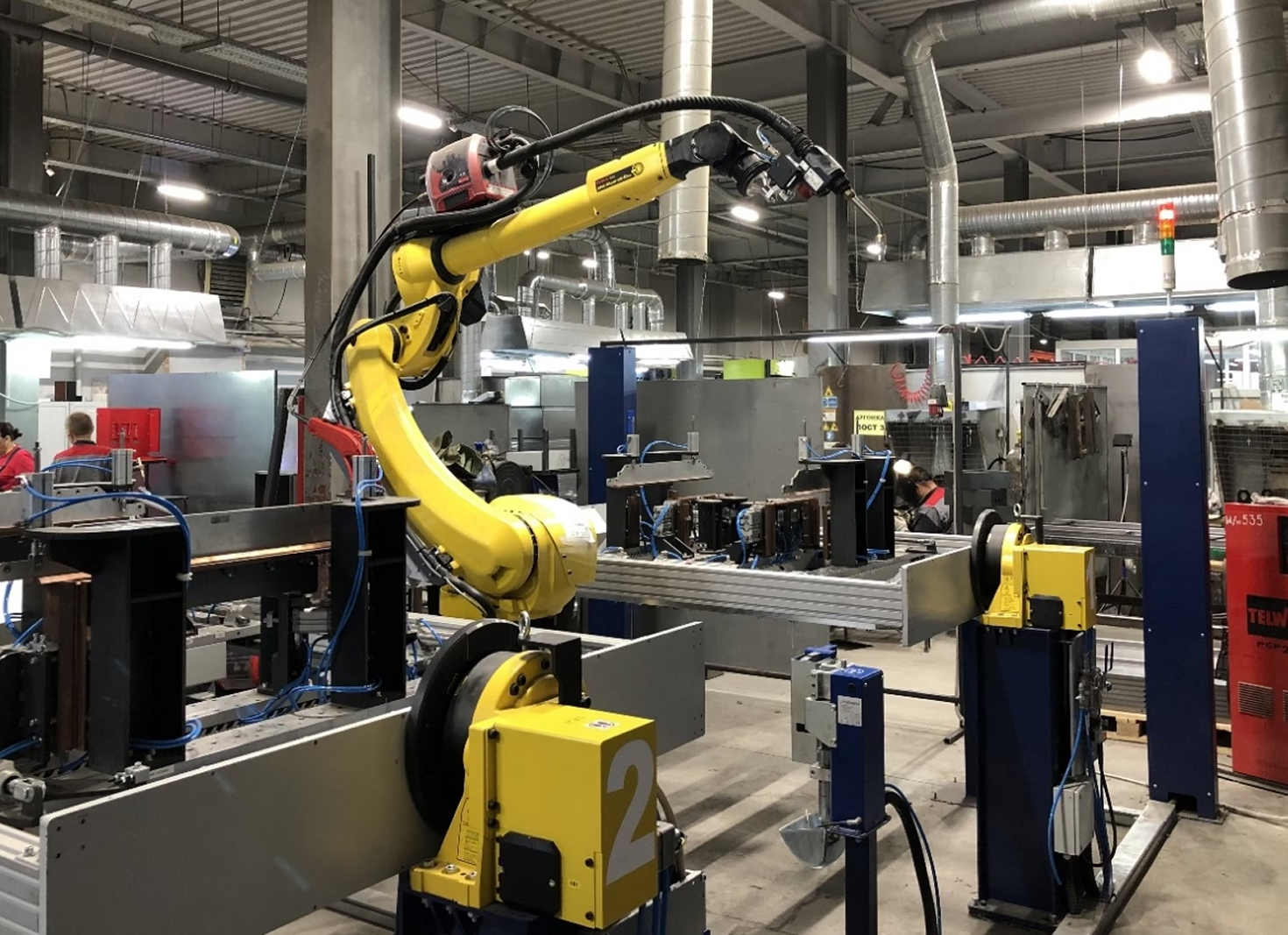
The robotic complex is designed for sequential assembly and welding of thin-sheet metal products, mounted on two independent automated fixtures. Copper elements and stops of the fixtures have liquid cooling (implemented via an industrial chiller), which effectively removes heat from the workpiece throughout the welding cycle. Each of the two fixtures is adjustable and supports 6 product sizes.
Purpose: welding of electrical cabinets
Material: steel
Material thickness: 1.0; 1.5 mm
Number of product sizes: 6
Minimum workpiece dimensions (L×W×H): 400×300×220 mm
Maximum workpiece dimensions (L×W×H): 1200×750×300 mm
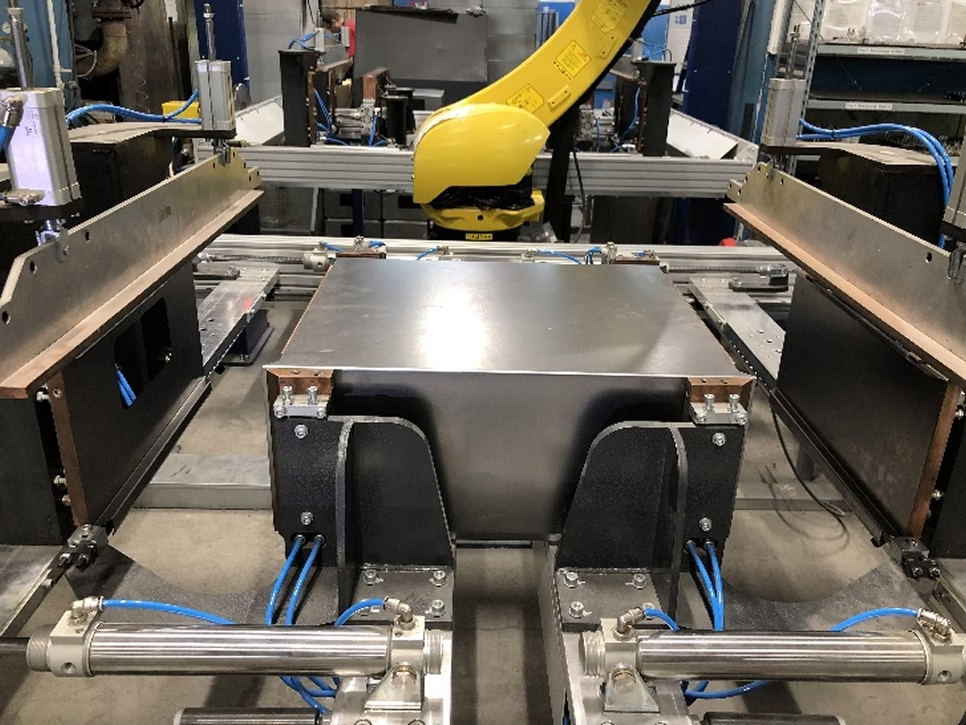
General View of the Complex
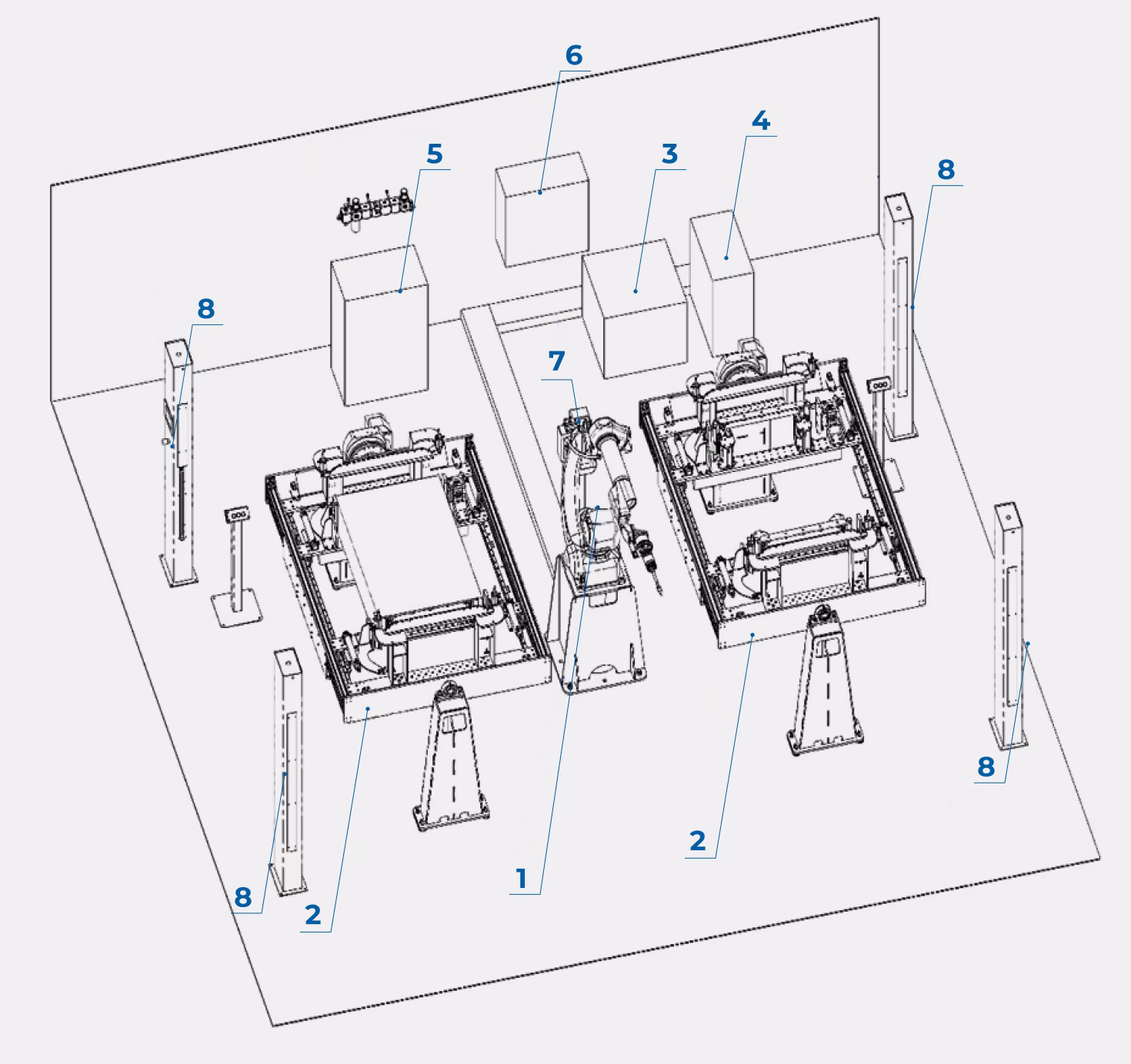
Main Components of the Complex
- Industrial robot
- Set of automated fixtures:
- assembly-welding fixture set
- single-axis positioner
- Industrial robot controller
- Welding power source
- Industrial chiller
- Control cabinet
- Welding torch cleaning station
- Protective light barriers
System Components
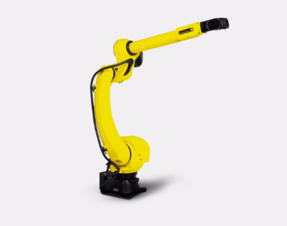
Industrial Robot Manipulator
Type — articulated anthropomorphic
Number of axes — 6
Payload — 12 kg
Position repeatability — ±0.03 mm
Working radius — 2272 mm
Average power consumption (including 5 additional axes) — 15 kW
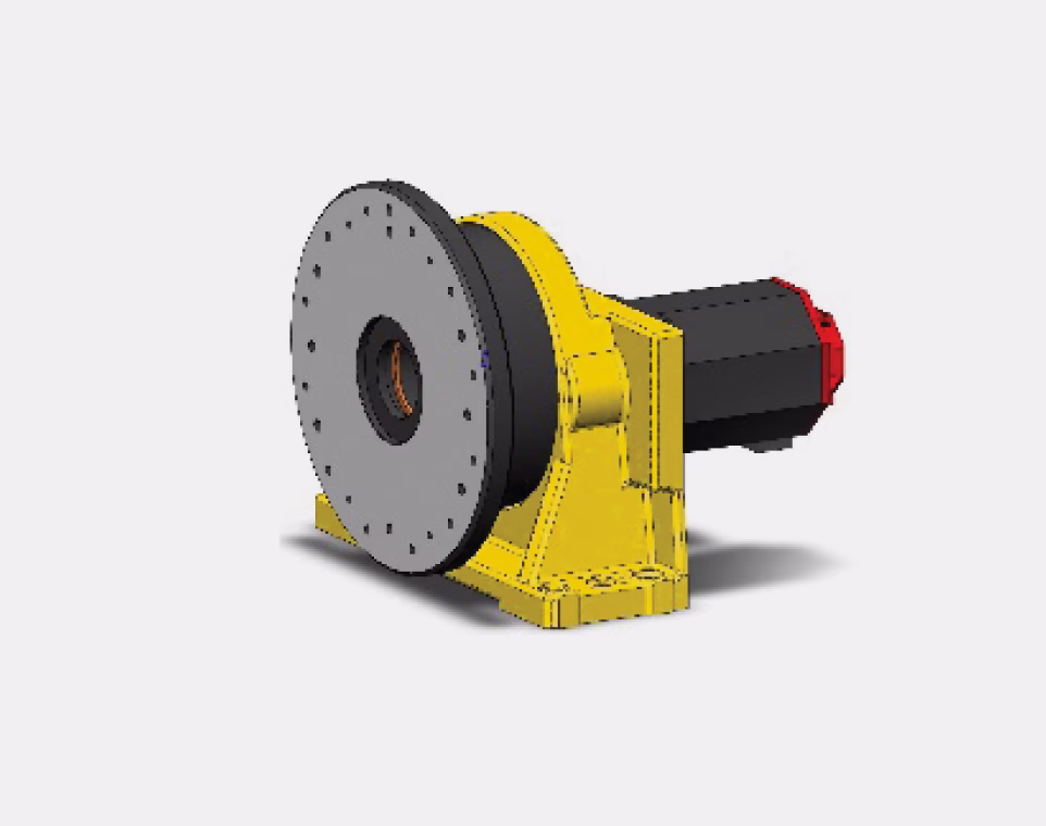
Single-Axis Positioner
Number of axes — 1
Maximum payload — 500 kg
Maximum torque — 735 N·m
Repeatability — ±0.02 mm
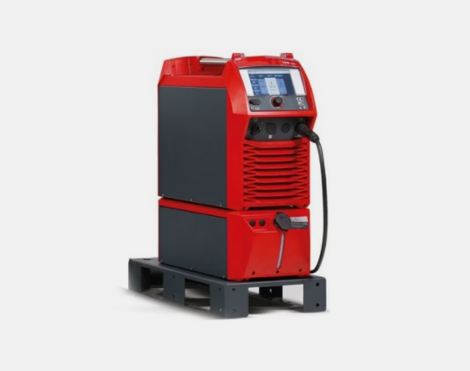
Welding Power Source
Torch cooling — liquid
Welding current range — 3–500 A
Welding current at 10 min./40 °C (duty cycle): 40% 500 A, 60% 430 A, 100% 360 A
Output voltage range (MIG/MAG) — 14.2–39.0 V
Open-circuit voltage — 71 V
Power consumption in standby — 34.1 W
Efficiency at 500 A/40 V — 89%
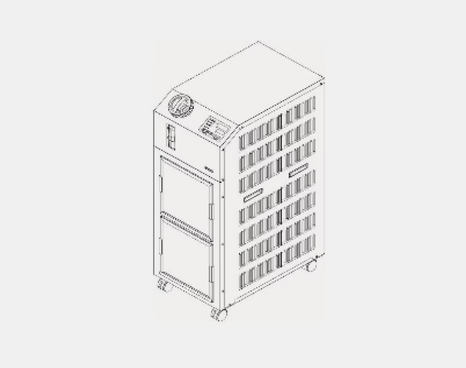
Industrial Chiller
Cooling capacity — 4.5 kW
Pump operating pressure, 23 l/min / 28 l/min — 0.21 MPa / 0.28 MPa
Pump flow rate, 50 Hz / 60 Hz — 23 l/min / 28 l/min
Cooling liquid temperature — 5–40 °C
Temperature stability — ±0.1 °C
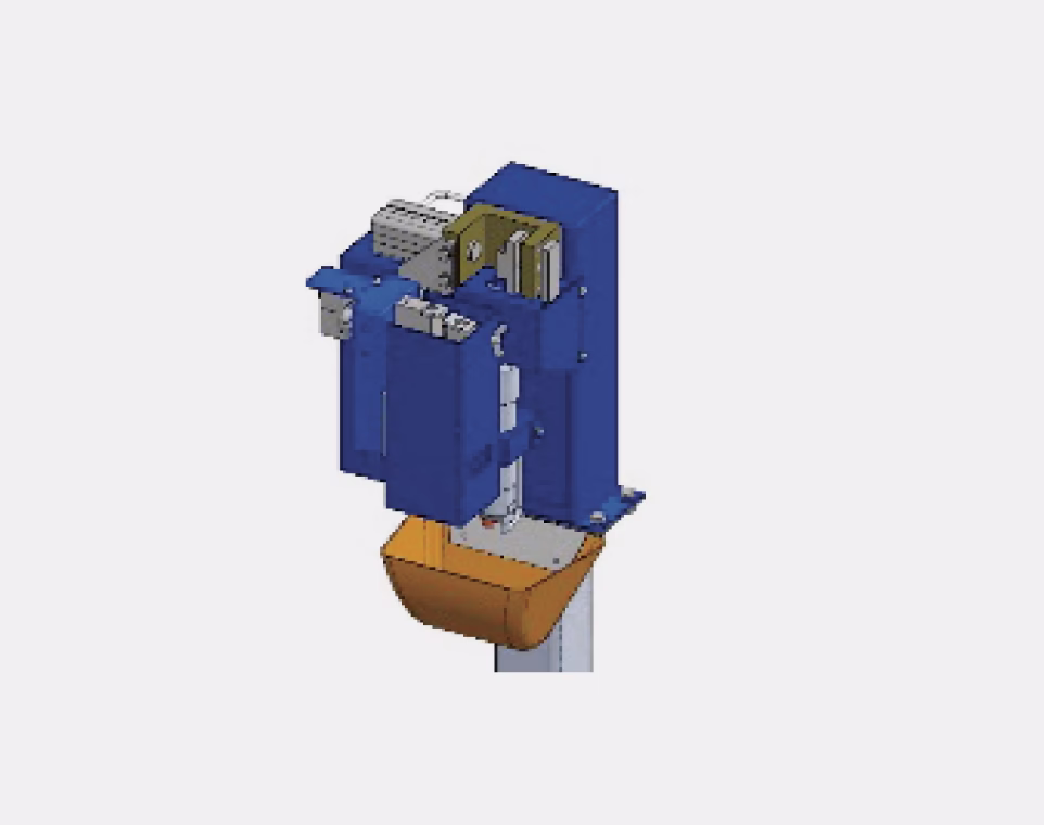
Welding Torch Cleaning Station
Wire trimming module cycle time — 2–3 s
Nozzle cleaning module cycle time — 3–4 s
Liquid injection module cycle time — 2–3 s
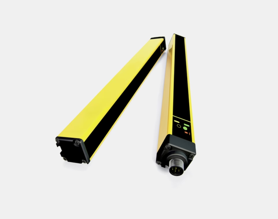
Safety Light Barriers
Number of beams — 2 pcs.
Response time — 2.5 ms
Protected height — 500 mm
Total curtain height — 510 mm
Maximum distance between receivers — 12 m
CMT (Cold Metal Transfer) Welding Process
The CMT (Cold Metal Transfer) process enables "cold" metal transfer during welding (compared to the conventional MIG/MAG process). When a short-circuit is first detected, the power source reduces the welding current to the minimum allowable value; droplet detachment occurs due to the reverse (mechanical) movement of the welding wire. Metal transfer is performed at low current values, ensuring minimal heat input.
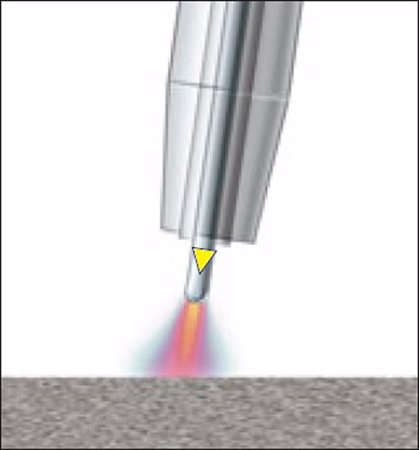
During the arc burning phase, the filler material is transferred into the weld pool.
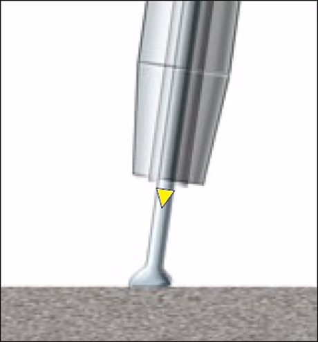
When the filler material immerses into the pool, the arc extinguishes. The welding current decreases.
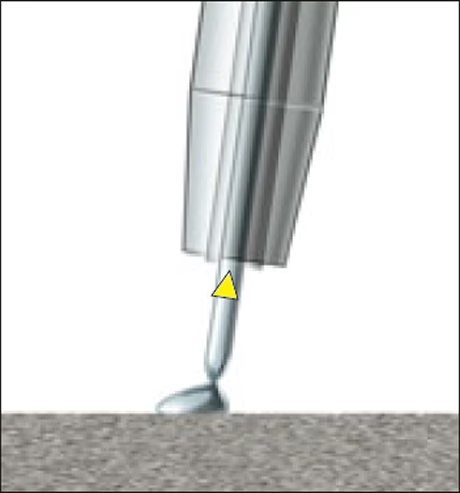
The reverse wire movement helps detach the droplet during the short-circuit. The short-circuit current is maintained at a low level.

The wire movement direction changes, and the process starts over.
Operation of the Complex

Automated fixture #1, set of stops for cabinet size #2

Automated fixture #2, set of stops for cabinet size #5

Installing the side panels of the cabinet

Installing the side panels of the cabinet
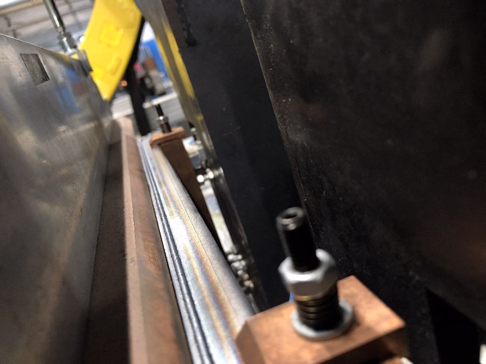
Fixing the cabinet in the fixture before starting the welding cycle
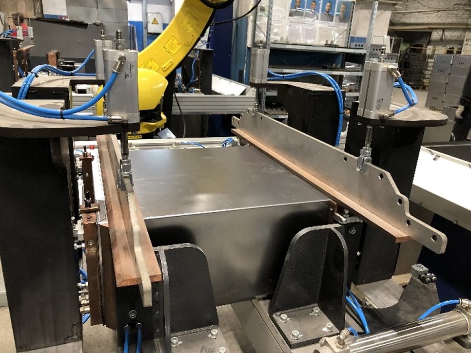
Fixing the cabinet in the fixture before starting the welding cycle
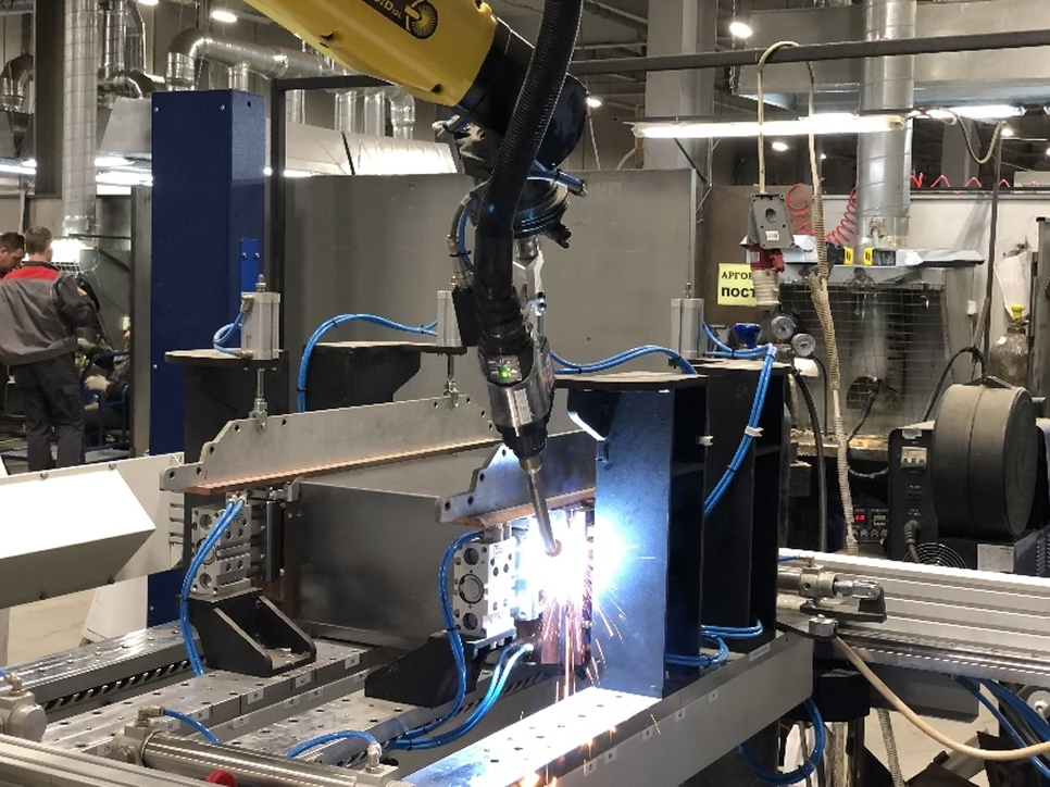
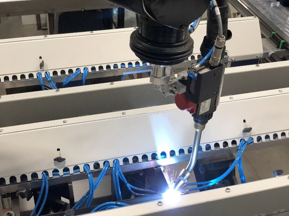
Vertical seam welding process, welding speed Vw=200 cm/min
Vertical seam welding process, welding speed Vw=200 cm/min
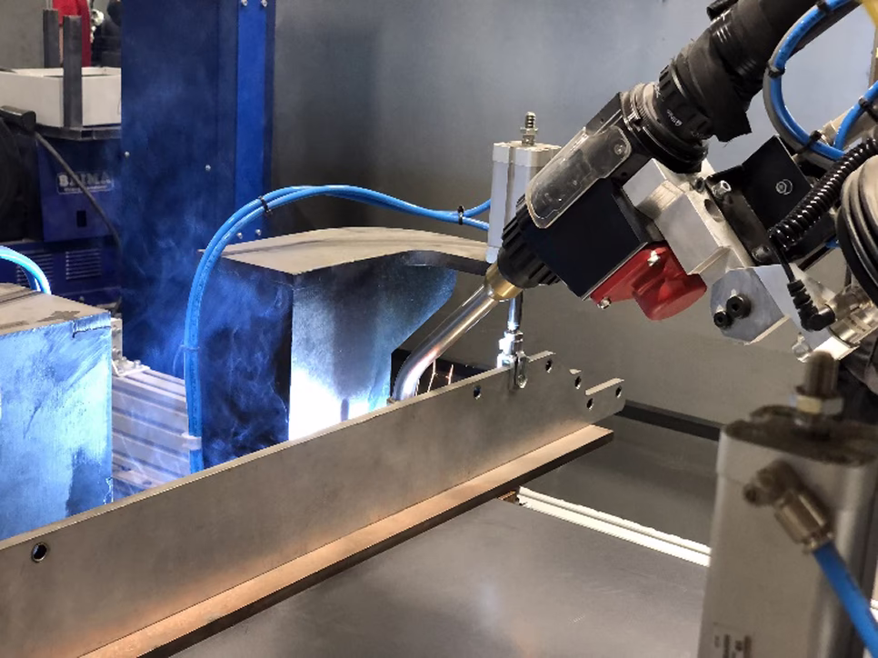
Flat position seam welding process, Vw=150 cm/min

Flat position seam welding process, Vw=150 cm/min
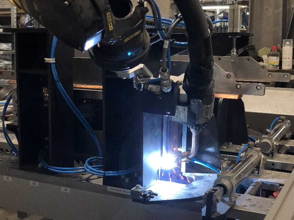
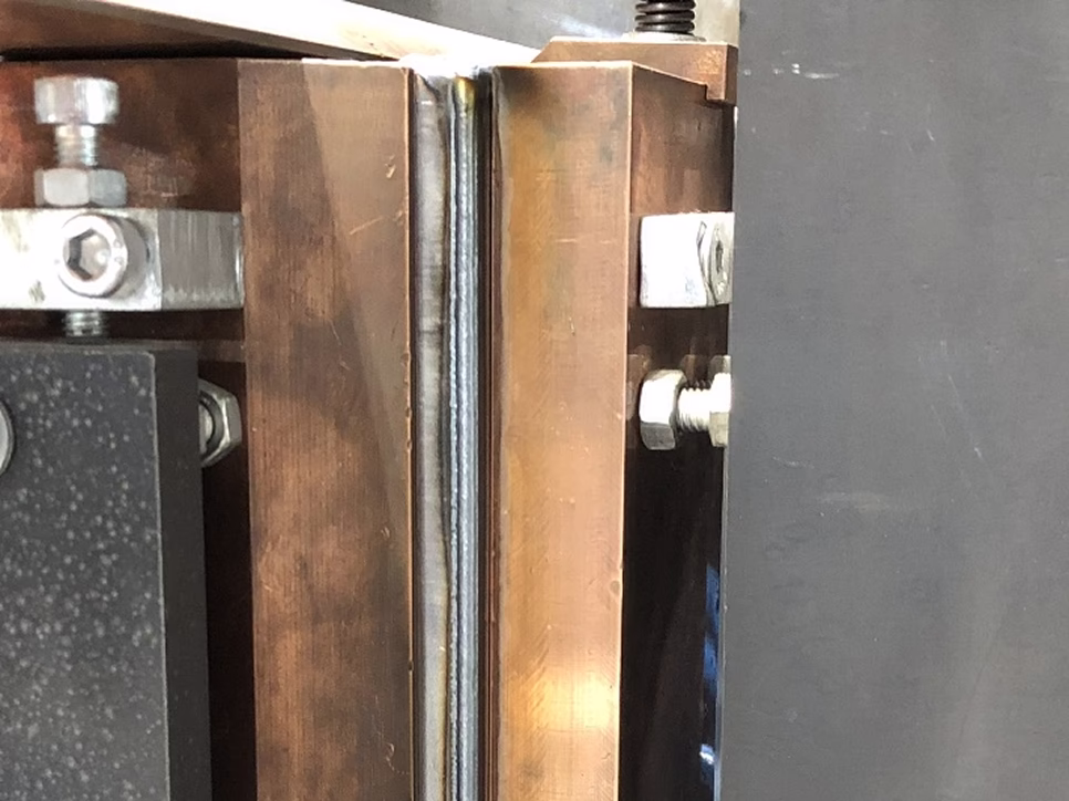
Welding the vertical seam from the inside of the cabinet

Welded cabinet in the fixture
Welded seam, PA position, Vw=150 cm/min
Welded seam, PG position, Vw=200 cm/min
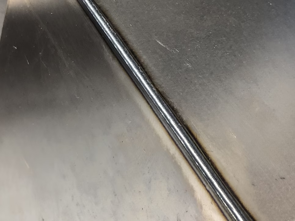
Welded seam, PG position, Vw=200 cm/min
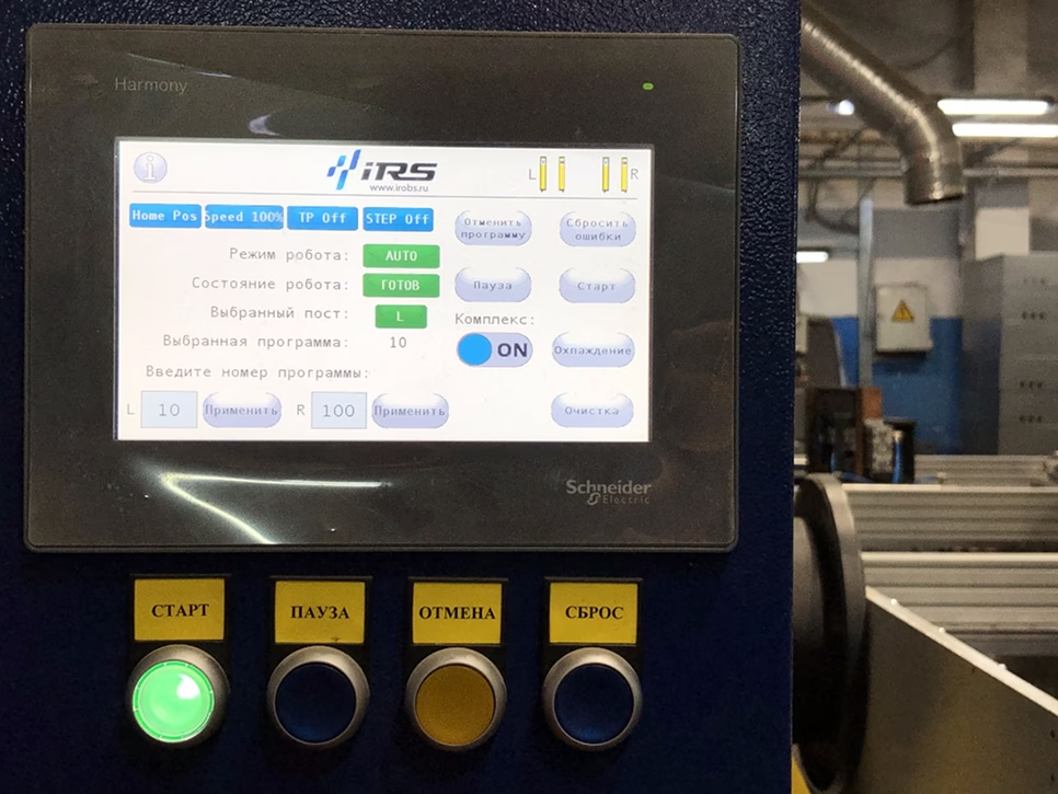
Operator control panel
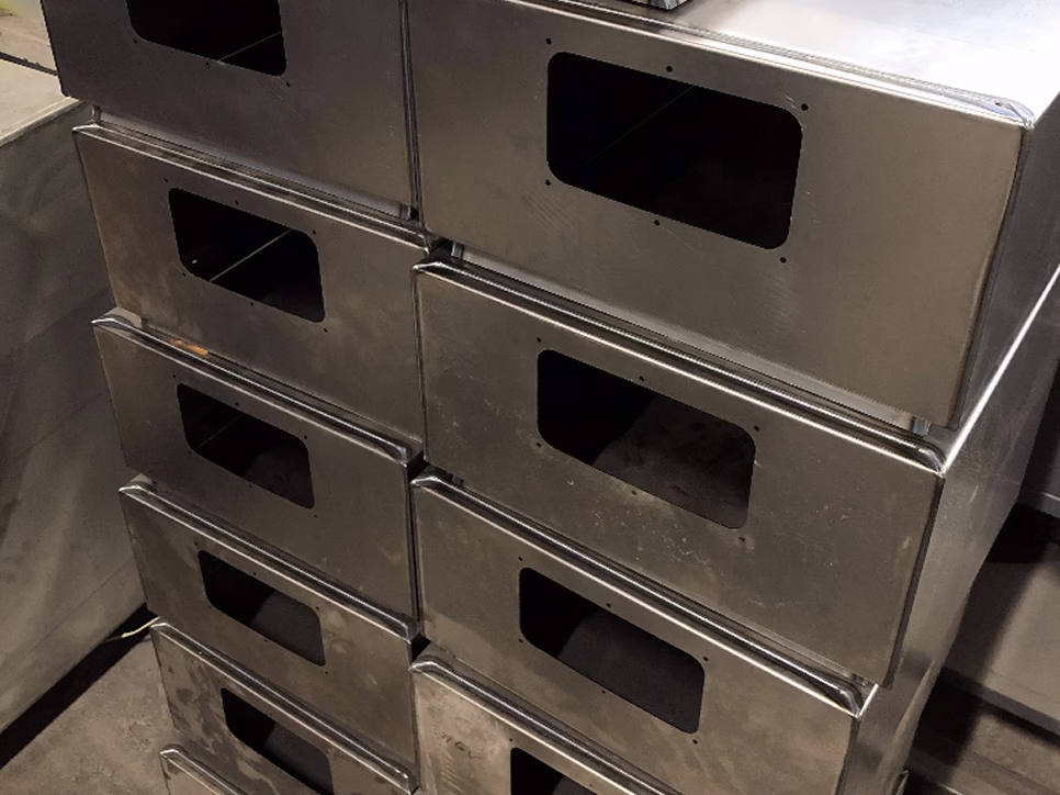
Welded products
Gallery of completed projects


