Automated Pipe Cladding System
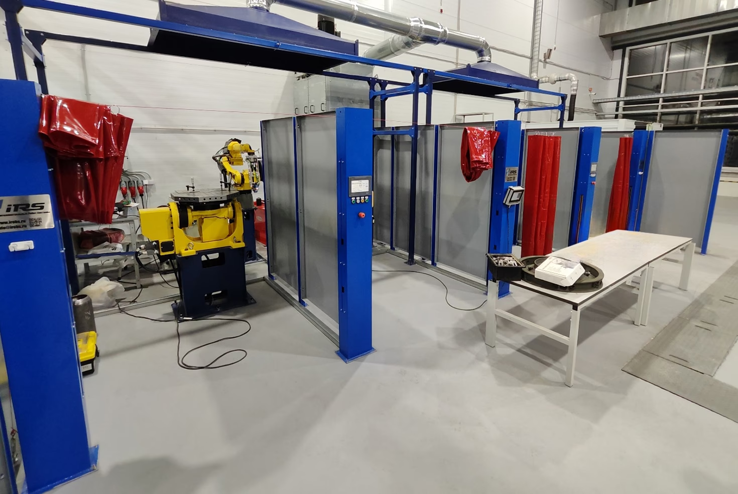
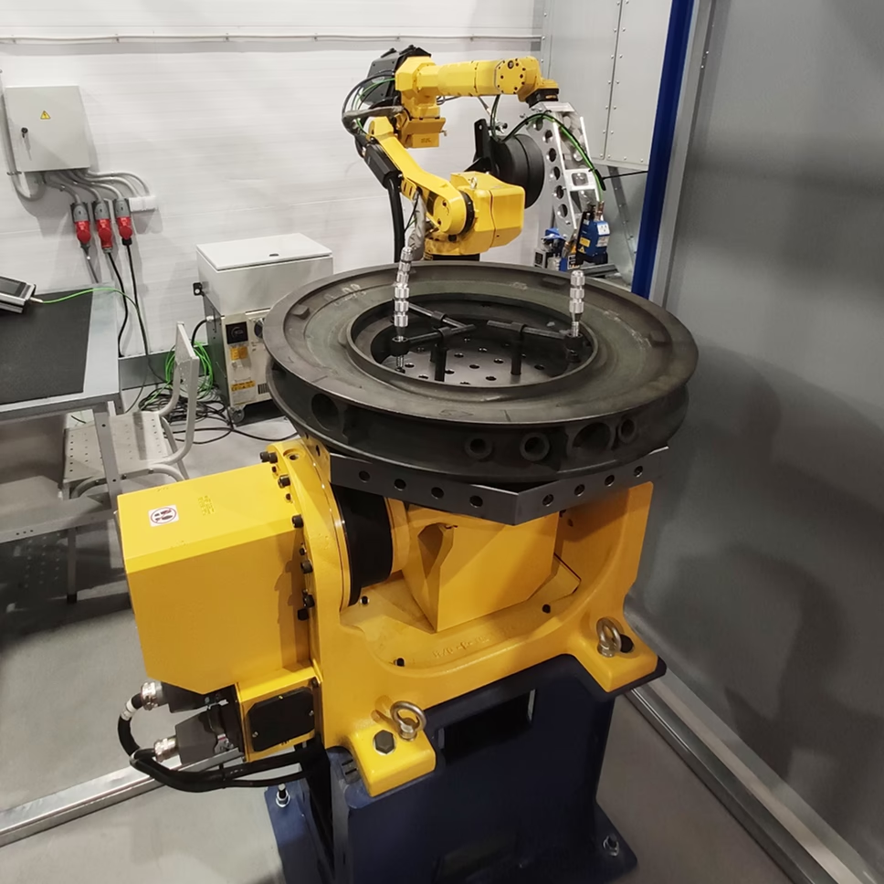
The installation is intended for welding components of aircraft and space engines. The installation is a system consisting of two workstations. Each workstation is equipped with two manipulators and a robot connected to welding units. A fume extraction system is installed above both workstations, providing ventilation throughout the entire operation of the system. Both robots are equipped with a laser seam tracking system. One of the welding units is equipped with the Cold Metal Transfer (CMT) function, enabling the welding of thin sheet metal.
Product application: special-purpose, civil
Workpiece material: structural, heat-resistant, and stainless steels
Welding process type: gas-shielded arc welding with a consumable electrode
General View of the System
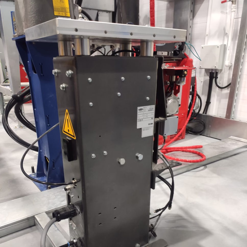
Standard Workstation
thickness of welded parts per pass: 2...4 mm
applicable
welding wire diameter: 0.8...1.6 mm
Applicable welding modes
Pulse, Standard, Job mode
CMT Workstation
thickness of welded parts per pass: 0.5...2.5 mm
applicable
welding wire diameter: 0.8...1.2 mm
Applicable welding modes:
CMT Pulse, CMT Standard, Pulse, Standard, Job mode
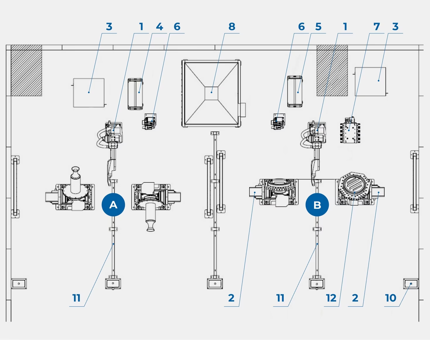
- Industrial manipulator
- Welding positioner
- Robot controller
- Welding power source
- Welding power source
- Torch cleaning station
- Tool change station
- Fume extraction system
- Exhaust hood
- Laser barrier stand
- Protective fencing
- Welding table
System Components
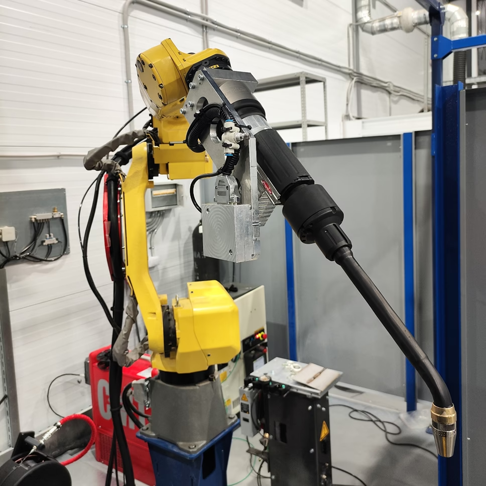
Manipulator with replaceable necks and SMT technology
Mechanism type — 6-axis robot
Maximum payload — 6 kg
Maximum reach (without end effector) — 1632 mm
Tool positioning repeatability according to ISO 9283 — ±0.08 mm
Axis rotation angles 1 / 2 / 3 / 4 / 5 / 6 — 360/250/445/380/380/720°
Maximum axis speed 1 / 2 / 3 / 4 / 5 / 6 — 210/190/210/400/400/600 °/s
Manipulator with META tracking system
Mechanism type — 6-axis robot
Maximum payload — 6 kg
Maximum reach (without end effector) — 1632 mm
Tool positioning repeatability according to ISO 9283 — ±0.08 mm
Axis rotation angles 1 / 2 / 3 / 4 / 5 / 6 — 360/250/445/380/380/720°
Maximum axis speed 1 / 2 / 3 / 4 / 5 / 6 — 210/190/210/400/400/600 °/s
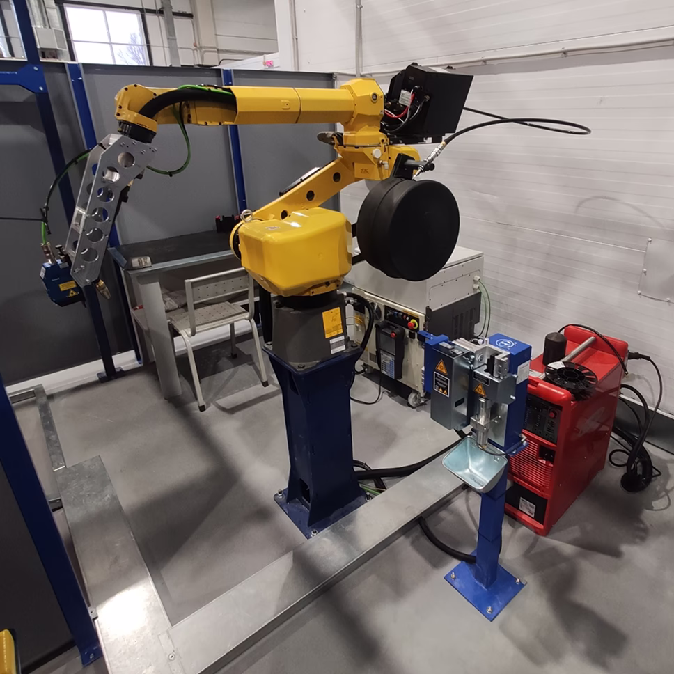
Welding positioner
Number of axes — 2
Maximum load capacity — 500 kg
Axis rotation angles 1 / 2 — 270/480°
Maximum rotation speed of axes 1 / 2 — 20/31.7 rpm
Repeatability — 0.05 mm
Weight — 295 kg
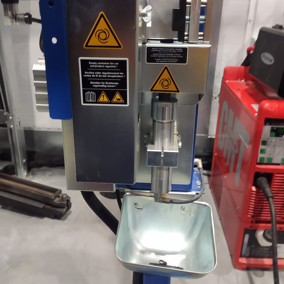
Torch cleaning station
Wire cutting module time — 2–3 s
Nozzle cleaning module time — 3–4 s
Fluid injection module time — 2–3 s
Tool change station
Nominal pressure — 6/87.02 bar/psi
Tool change time — 25–30 s
Protection class — IP 20
Dimensions (L×W×H) — 477×759×789 mm
Weight — 60 kg
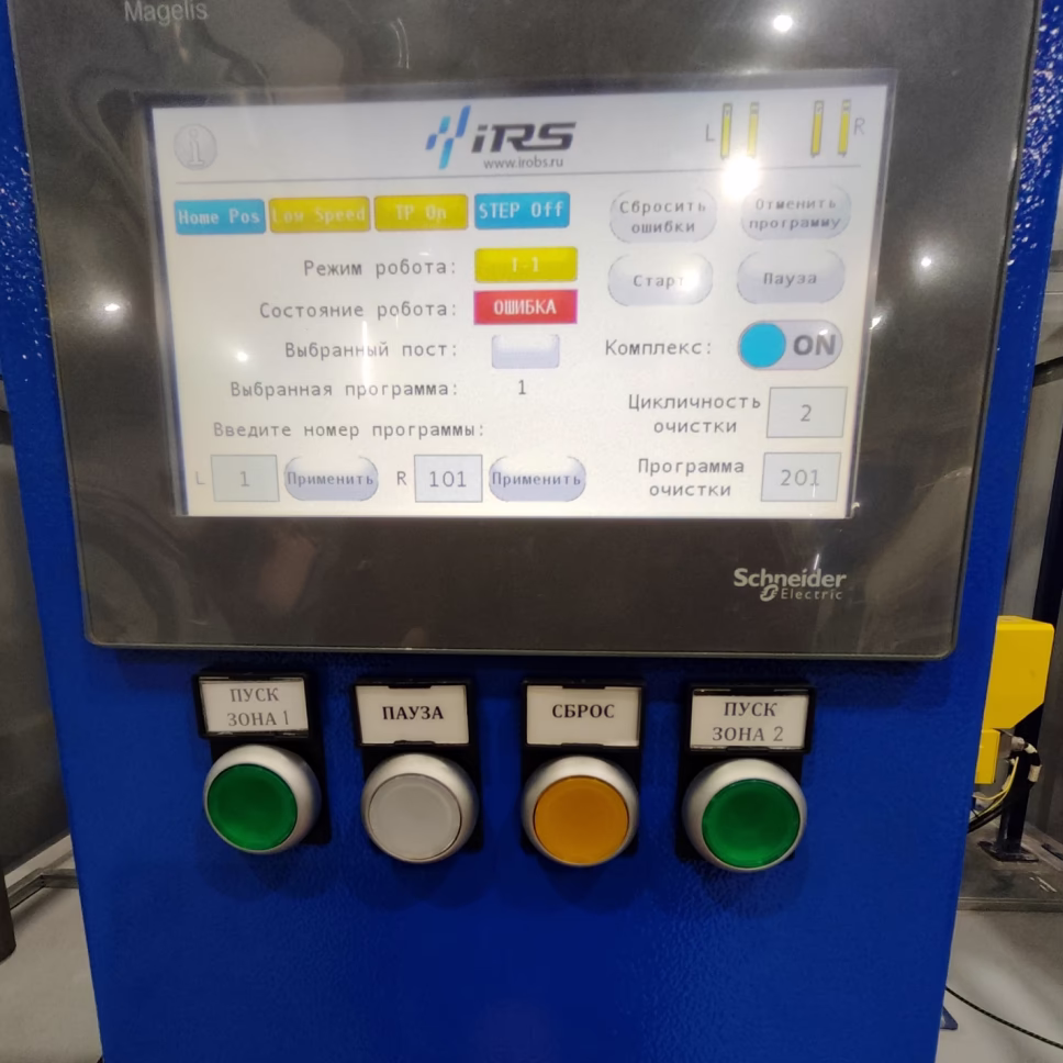
Operator control panel
Human-machine interface type — graphic control panel with a color touchscreen HMI
Touchscreen size — 7 inches
CMT (Cold Metal Transfer) Welding Process
The CMT (Cold Metal Transfer) process enables "cold" metal transfer during welding (compared to the conventional MIG/MAG process). Upon the first detection of a short circuit, the power source reduces the welding current to the minimum allowable value; droplet detachment occurs due to the reverse (mechanical) movement of the welding wire. Metal transfer occurs at low current values, ensuring minimal heat input.
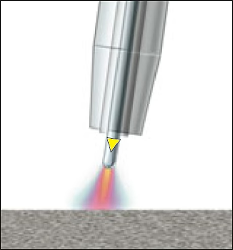
During the arc burning phase, the filler material is transferred into the weld pool.
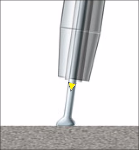
When the filler material is immersed in the pool, the arc extinguishes and the welding current decreases.
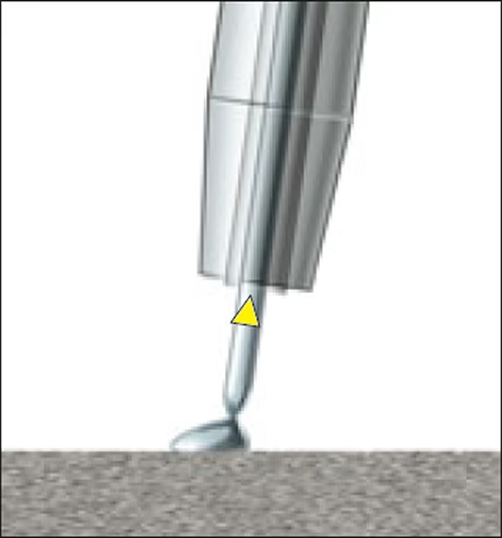
Reverse wire movement promotes droplet detachment during the short circuit. The short-circuit current is maintained at a low level.
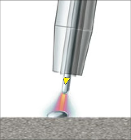
The wire movement direction changes, and the process starts again.
Gallery of completed projects


